TM 1-8415-216-12&P
f. V-1 ANVIS Center Mount (Figure 2-5).
Ensure that the ANVIS system mounted on your HGU-56/P is working
properly in accordance with TM 11-5855-263-10 prior to using it.
Failure to check the ANVIS or to be able to see the low battery warn-
ing light when using the ANVIS may result in a critical loss of equip-
ment use.
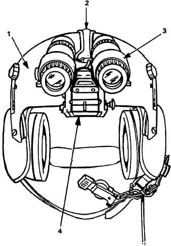
The V- 1 ANVIS center-mount AN/AVS-6(V) 1 (4) attaches to the dual visor housing
(1) through pre-drilled holes. From this location, the AN/AVS-6 (3) can be deployed
or stowed. When the ANVIS is in the stowed position, either visor can be de-
ployed. The ANVIS power pack is mounted to the rear of the helmet with hook-and-
pile fastener material. The electrical connection is made at the rear of the cover,
access (2). (The cover, access houses the ANVIS cable.) For ANVIS operational
and maintenance information, refer to TM 11-5855-263-10.
Figure 2-5. ANVIS Dual Visor Assembly with Center-Mount ANVIS
2-4