TM 1-7010-386-12&P
CONTROLS AND INDICATORS
0004 00
Power Converter/Battery Charger
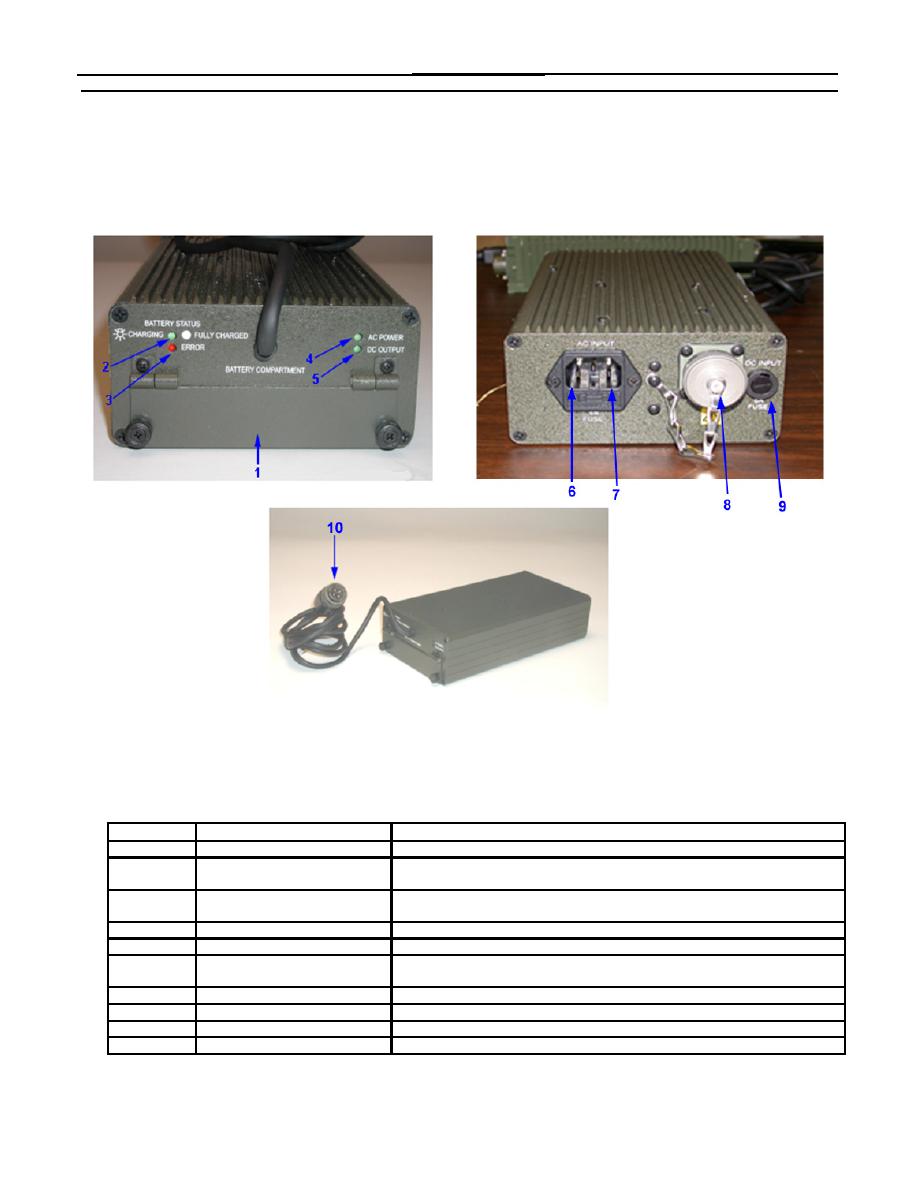
Figure 5 illustrates the controls, indicators, and connectors located on the Power Converter/Battery Charger with a
brief description of each of their functions.
Figure 5. Power Converter/Battery Charger Controls and Indicators
Item No.
Item Name
Description and Use
1
Battery Compartment
Provides a slot to insert the battery into charger to be charged.
2
Charge Indicator
Flashes to indicate the battery is being charged. Lit steadily to indicate the
battery is fully charged.
3
ERROR Indicator
Lit to indicate the battery is not within temperature or voltage specification and
cannot be charged.
4
AC POWER Indicator
Lit to indicate that AC power is applied.
5
DC POWER Indicator
Lit to indicate that DC output is functioning properly.
6
AC Input Connector
Provides interface to accept 110-220 VAC at 47-440 Hz from commercial
power source.
7
AC Fuse
AC Fuse and spare AC fuse located here.
8
DC Input Connector
Provides interface to accept 18-32 VDC from military vehicle.
9
DC Fuse
DC fuse located here.
10
DC Output Cable
Provides 24 VDC from the Power Converter/Battery Charger to the PCU.
0004 00-5


