TM 1-7010-386-12&P
CONTROLS AND INDICATORS
0004 00
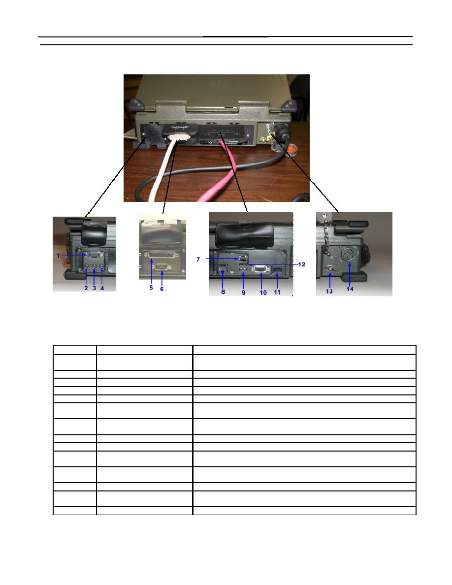
Figure 3 illustrates the connectors located on the back of the PCU with a brief description of each of their
functions.
Figure 3. PCU Back Connectors
Item No.
Item Name
Description and Use
1
Serial Port, Com 1
Both serial ports are configured for RS-232 operation, but can be configured for
RS-485 operation.
2
Line In Connection
The connector uses a 1/8 inch min-stereo jack.
3
Amplified Audio Out
The connector uses a 1/8 inch min-stereo jack.
4
Microphone In
The connector uses a 1/8 inch min-stereo jack.
5
Parallel Port
The 25 pin connector is provided for printer connection or other parallel devices.
6
Serial Port Com 2
Both serial ports are configured for RS-232 operation, but can be configured for
RS-485 operation.
7
10/100 Base-T Ethernet Port
The Ethernet port is IEEE-802.3 compliant and is used to connect to a Local
Area Network (LAN).
8
Modem Port
56.6K
9
USB 2 Port
The port is USB 2.0 compliant.
10
External Video Monitor
This connection is for an external video monitor with resolution of up to 1280
Connector
pixels X 1024 pixels. 16.7 million colors are supported.
11
Infrared Transmitter/Receiver
A two-way wireless infrared Data Association (IrDA) 1.1/1.0 is provided for use
with remote pointing devices and/or remote keyboard.
12
USB 1 Port
The port is USB 2.0 compliant
13
Ground Stud
The ground stud is provided to allow other electronic items to have a common
ground with the PCU.
14
Input Power Connector
Provides connection to a 18-32 VDC, 110 W maximum power source.
0004 00-3


