TM 1-1510-225-10
2-46
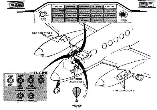
Figure 2-14. Engine Fire Detection System T3 F3 ANG
The test switch is on the copilot's left subpanel,
and is placarded TEST SWITCH FIRE DET OFF / 1 / 2
/ 3. The three test positions for the fire detector
system are located on the right side of the switch (1 / 2
/ 3). When the switch is rotated from OFF (down) to
any one of these three positions, the output voltage of
a corresponding flame detector in each engine
compartment is increased to a level sufficient to signal
the amplifier that a fire is present. The following
should illuminate: the flashing red pilot and copilot
MASTER WARNING lights, and the red warning
annunciator panel lenses placarded L ENG FIRE and
R ENG FIRE. The system may be tested either on the
ground or in flight. The TEST SWITCH should be
placed in all three positions, in order to verify that the
circuitry for all six fire detectors is functional. Failure of
all the fire detection system annunciators to illuminate
when the TEST SWITCH is in any one of the three fire
detector test positions indicates a malfunction in one
or both of the two detector circuits (one in each
engine) being tested by that particular position of the
TEST SWITCH.
2-25. ENGINE FIRE EXTINGUISHER SYSTEM R .
NOTE
There is no fire extinguisher system on the
C-12 T3 / F3 model aircraft.
a. Description. The engine fire extinguisher
system consists of a supply cylinder, an explosive
squib, and a valve located in each of the main gear
wheel wells. Refer to Figure 2-15. A gauge calibrated
in psi is provided on each supply cylinder for
determining the level of charge. The extinguishing
agent charge level should be checked during each
preflight. When fired, the explosive squib opens the
valve, releasing all of the pressurized extinguishing
agent into a plumbing network. The plumbing network
terminates in spray nozzles, strategically located in the
probable fire areas of the engine compartment, which
distribute the extinguishing agent.


