TM 1-1510-225-10
2-45
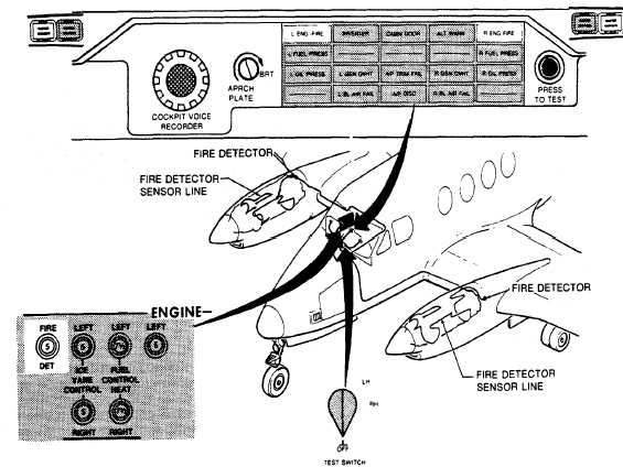
Figure 2-13. Engine Fire Detection System T3 F3 OSA
Testing system integrity, availability of power,
and the alarm lights, (L and R ENG FIRE and
MASTER WARNING) is accomplished by a single
rotary switch located on the copilot's left subpanel.
The switch, placarded TEST SWITCH FIRE DET OFF
/ RH / LH. OFF is at the six o'clock position, RH at the
three o'clock and LH at the one-thirty position. At both
the RH and LH positions, electrical current flows from
a 5 amp circuit breaker placarded FIRE DET located
on the right side circuit breaker panel, through the
engine fire detector circuitry to the integrity switch
contacts in the respective responder unit, causing the
alarm lights to illuminate, thereby assuring the crew
that the detector is operational. If the circuit breaker
opens, the system will not operate during test, or
activate the annunciator lights if the detector cable
senses an over-temperature condition. The system
may be tested either pre/post flight, or in flight as
desired.
c. Description T3 F3 ANG . The ANG fire
detection system, Figure 2-14, consists of three
photoconductive cells for each engine; a control
amplifier for each engine; two red warning lights on the
warning annunciator panel, L ENG FIRE and R ENG
FIRE; a test switch on the copilot's left subpanel; and a
circuit breaker placarded FIRE DET on the right side
panel. The six photoconductive cell flame detectors
are sensitive to infrared radiation. They are positioned
in each engine compartment so as to receive both
direct and reflected rays, thus monitoring the entire
compartment with three photocells.
Conductivity through the photocell varies in
direct proportion to the intensity of the infrared
radiation striking the cell. As conductivity increases,
the amount of current from the electrical system
flowing
through
the
flame
detector
increases
proportionally. To prevent stray light rays from
signaling a false alarm, a relay in the control amplifier
closes only when the signal strength reaches a preset
alarm level. When the relay closes, the appropriate
left or right warning annunciators illuminate. When the
fire has been extinguished, the cell output voltage
drops below the alarm level and the relay in the control
amplifier opens. No manual resetting is required to
reactivate the fire detection system.


