TM 1-1510-225-10
2-49
2-28. AUTO IGNITION SYSTEM.
If armed, the auto ignition system automatically
energizes both igniter plugs of either engine, should an
accidental flameout occur. The system is not essential
to normal engine operation, but is used to reduce the
possibility of power loss due to icing or other
conditions. Each engine has a separate ENG AUTO
IGNITION control switch and a green annunciator,
LEFT IGNITION ON and RIGHT IGNITION ON,
located on the caution/advisory annunciator panel.
Auto ignition is accomplished by energizing both
igniter plugs in each engine.
NOTE
The system should be turned OFF during
extended ground operation to prolong the
life of the igniter plugs.
a. Auto Ignition Switches. Two switches
located on the pilot's subpanel, each placarded ENG
AUTO IGNITION ARM / OFF LEFT / RIGHT, control
the auto ignition systems. The ARM position initiates
a readiness mode for the auto ignition system of the
corresponding engine. The system is disarmed when
in the OFF position. The corresponding 5-ampere
LEFT or RIGHT IGNITOR POWER circuit breaker on
the left sidewall circuit breaker panel protects each
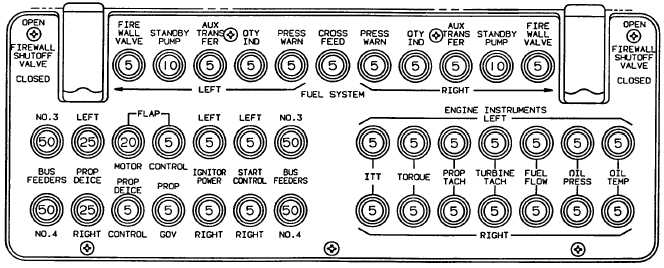
circuit. Refer to Figure 2-16.
b. Auto Ignition Annunciators. If an armed
auto ignition system changes from a ready condition to
an operating condition (energizing the igniter plugs in
the engine) the corresponding engine's green L or R
IGNITION ON annunciator will illuminate, indicating
that the igniters are energized. The auto ignition
system is triggered from a ready condition to an
operating condition when engine torque drops below
approximately 20%. Therefore, when an auto ignition
system is armed, the igniters will be energized
continuously during the time when an engine is
operating at a level below approximately 20% torque.
2-29. ENGINE STARTER-GENERATORS.
One
starter-generator
is
mounted
on
the
accessory drive section of each engine. Each starter-
generator is able to function either as a starter or as a
generator. In the starter function, 24 Vdc is required to
power rotation. In the generator function, each unit is
capable of 250 amperes dc output. When the starting
function is selected, the starter control circuit receives
power from either the aircraft battery or an external
power source through the respective 5-ampere LEFT
or RIGHT START CONTROL circuit breaker, located
on the left sidewall circuit breaker panel. When the
generating function is selected, the starter-generator
provides electrical power.
2-30. ENGINE INSTRUMENTS.
The engine instruments are arranged vertically
near the center of the instrument panel. Refer to
Figure 2-17, Sheets 1 through 8. The circuit breakers
for all engine instruments are located on the left
sidewall circuit breaker panel. All engine instrument
circuit breakers are fed through the 7 1/2-ampere
LEFT and
RIGHT ENG INSTR POWER circuit
breakers located on the right sidewall circuit breaker
panel.
Figure 2-16. Left Sidewall Circuit Breaker Panel