TM 1-1510-225-10
3C-14
(a) Navigation Displays. The navigation
displays are selected by placing the rotary switch on
the control unit to NAV. In this mode, Data NAV
enables
data
from
two
independent
navigation
sources, if available, and displays either or both on the
indicator. Additionally, the HSI's OBS knobs can be
used to control a course line about the VOR when
selected from the control unit.
The current magnetic heading of the aircraft is
displayed on a scale at the top of the screen to
establish a visual reference point for pilot orientation.
Selected heading can also be displayed graphically on
the indicator when HDG is activated on the control
unit.
When the appropriate designator is selected, via
the control unit, the active VOR establishes a
reference point for the designator. The designator
controls on the control unit will then move the
designator symbol to any point on or off the screen
within approximately 423 nm of the VOR and display
the radial and distance to the designator from the
VOR. A solid line connects the designator position to
the VOR. The homed designator position is the VOR.
The designator can be selected to work with the
VOR for either of the navigation sources via the NAV 1
/ NAV 2 slide-switch on the control unit. Alphanumeric
readout of radial and distance of the designator from
the VOR, as well as bearing (magnetic) and distance
to the designator from the aircraft, is displayed on the
screen.
The designator can be used to create a waypoint
on the display from a VOR or TACAN. Since the
designator is fixed geographically relative to VOR, it
can be used similar to a waypoint, although not
coupled to GDI.
When the
HOME button is pressed, the
designator is returned to the VOR and the readout of
distance to designator and radial of designator with
respect to VOR goes to zero.
When the designator is activated for one VOR
and then the other VOR selected, the system will
retain the data for the first navigation source in
memory. An asterisk in the color of the first navigation
source will be displayed in the top left hand of the
screen to the right of the Station-t o-Designator (S-D)
legend, provided that data on the position of the first
navigation source is present. This asterisk will be
removed when position data is lost.
(b) Graphic
Displays.
The
graphic
display symbols are Superimposed on displays of
radar returns. Refer to Figure 3C-8.
Figure 3C-8. Graphic Display Symbols
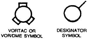
1 Ground Station Symbol. The
VORTAC or VOR/DME symbol is accompanied by a
readout of the station radial and ID, displayed in the
lower left portion of the display.
2 DESIGNATOR SYMBOL. The
DESIGNATOR SYMBOL is selected to work with the
VOR for either station by the control unit.
3 Compass Heading. The current
magnetic heading of the aircraft is displayed on a
scale at the top center of the screen. A selected
heading line may also be displayed by pressing the
HDG switch on the Control Unit.
4 Course Lines. The waypoint and
ground station symbol course lines are displayed as
solid lines through the symbols and originate from a
position determined by the settings of the HSI(s) OBS
knobs.
5 DES NAV 1 / DES NAV 2 Slide
Switch. The designator IN / OUT and RAD controls
are used to move the designator symbol to any point
on or off the screen, with the VOR as reference, and
display radial and distance to the designator from the
VOR, whether or not the VOR station is within radar
range, as long as signals are being received. The S-D
readout is displayed in the upper left portion of the
display and the Aircraft-to-Designator (A -D) readout is
displayed in the lower right portion of the display. With
the designator in the home position, or positioned on
the VOR, a tick is displayed to indicate the direction of
OUT movement. This tick is removed once the
designator is moved out from the ground station
symbol. A solid line connects the designator symbol to
the VOR symbol. By pressing the HOME switch, the
designator is positioned on the VOR, with the tick
pointing to magnetic north.
(3) NAV Operation.


