TM 1-1510-225-10
3C-12
(h) Power Warning Flag – In view,
indicates power off, caged condition, open motor
winding, or loss of power. Retracted, indicates normal
operation.
(i) Roll Index – Rotates with aircraft to
provide measurement of angular displacement by the
roll pointer during maneuvers.
(3) Standby
Attitude
Indicator
Functions
ANG . Refer to Figure 3C-6.
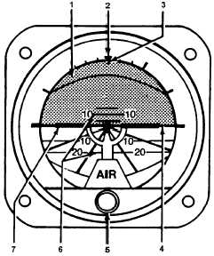
1. Attitude Sphere
2. Roll Index
3. Roll Pointer
4. Horizon Line
5. Pitch Knob
6. Pitch Scale
7. Symbolic Miniature Aircraft
Figure 3C-6. Standby Attitude Indicator ANG
(a) Attitude Sphere – Moves with respect
to the symbolic miniature aircraft reference to display
pitch and roll attitude.
(b) Roll Index – Rotates with aircraft to
provide measurement of angular displacement by the
roll pointer.
(c) Roll Pointer – Indicates vertical in any
roll attitude.
(d) Horizon Line – Indicates earth’s
horizon relative to aircraft pitch attitude.
(e) Pitch Knob – Rotated to adjust the
miniature aircraft.
(f) Pitch
Scale
–
Measures
pitch
displacement of miniature aircraft.
(g) Miniature
Aircraft
–
Represents
aircraft nose and wings. Indicates roll and pitch
attitude relative to the horizon. Adjustable through
pitch knob for varying pitch attitudes.
3C-16. DATA NAV SYSTEM.
a. Introduction. The Data NAV equipment
enables the operator to use the color weather radar
indicator to display radar returns, checklists, or
navigation symbology/alpha-numeric. The navigation
data is derived from external VOR/DME, or TACAN
devices as selected by the two HSI source push
switches located outboard of each HSI. Refer to
Figure 3C-7.
The four principal display modes in which the
radar indicator operates are Radar Returns (WXD),
Navigation (NAV), Checklists, and Auxiliary.
b. Data NAV Switches and Controls.
(1) OFF / NORM INDEX / NORM LIST /
WXD / EMER INDEX / EMER LIST / NAV / AUX.
Rotary switch used to turn Data NAV Interface
Computer off or on by selection of checklist, weather
(WXD), navigation (either NAV or with weather), or
Auxiliary operation.
(2) NAV
1
–
The
pilot's
navigation
information is displayed via the latching push-button
switch, NAV 1 (green).
(3) DES IN / DES OUT – Momentary left-
right 3-position switch used to move the designator
along radial established by RAD control.
(4) NAV 2 – Latching push-button switch
used to select NAV 2 station (yellow).
(5) CS 1 – Latching push-button switch used
to select course line (green) and readout for NAV 1
station.
(6) CS 2 – Latching push-button switch used
to select course line (yellow) and readout for NAV 2
station.
(7) DES NAV 1 / DES NAV 2. Slide-switch
used to select designator for NAV 1 or NAV 2 station.