TM 1-1510-225-10
3C-11
information for at least 30 minutes after a total failure
of the aircraft electrical system.
The power supply contains sealed lead-acid
batteries with a rating of 5.0 ampere hours. During
normal operation, the aircraft 28 Vdc system supplies
power to the indicator and power supply batteries. In
the event aircraft electrical power fails, the power
supply will take over the duties of powering the attitude
indicator.
The attitude indicator is a 28 Vdc powered,
electrically driven gyro and contains an inverter circuit
board for converting the 28 Vdc input to 22 Vac 400
Hz for indicator operation. The power warning flag is
rotated out of sight by a flag motor that allows the flag
to display if one or more phases of power are
interrupted. The flag motor also allows the flag to
display if the PULL TO CAGE knob is in the caged
position. The rotor speed and the mechanical erection
system enable the indicator to provide a minimum of 9
minutes of useful attitude information after complete
electrical power interruption.
(2) ANG . The standby attitude i ndicator,
located on the extreme left center of the pilot's
instrument panel, is powered by engine bleed air and
provides a visual reference of the aircraft pitch and roll.
The attitude indicator is comprised of a self contained
gyro to erect the sphere which provides the pitch and
roll reference, an indicating symbol which represents
the aircraft, and a horizontal line behind the indicating
symbol which represents the horizon. The moveable
indicating symbol may be adjusted vertically to correct
for variations in level flight attitudes by a small knob
located on the front base of the indicator.
b. Controls, Indicators, and Functions.
(1) A three-position switch and a three-
legend annunciator unit, located below the indicator,
provide system control, test, and visual indication of
the system status. The three-position switch (normally
OFF), placarded ON / OFF / TEST, provides control
and test capabilities of the battery powered system.
While in the normal OFF position, the annunciator
placarded, AUX ARM, will be illuminated indicating the
system batteries are being maintained in a charged
condition and the system is in a standby (non-active)
mode. Placing in the TEST position activates a check
of the battery pack and illuminates the AUX TEST
annunciator. Placing in the ON position activates the
Standby Horizon Indicator system and illuminates the
AUX ON annunciator (provided the system circuit
breaker is set).
(2) Standby Attitude Reference Indicator
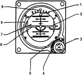
Functions OSA . Refer to Figure 3C-5.
1. Roll Pointer
2. Horizon Line
3. Caging/Pitch-Trim Knob
4. Trim Pointer
5. Pitch-Trim Scale
6. Miniature Aircraft
7. Drum
8. Power Warning Flag
9. Roll Index
Figure 3C-5. Standby Attitude Reference
Indicator OSA
(a) Roll Pointer – Indicates vertical in any
roll attitude.
(b) Horizon Line – Indicates earth's
horizon relative to aircraft pitch attitude.
(c) Caging / Pitch-Trim Knob – Pulled to
cage the indicator and rotated to adjust the miniature
aircraft attitude.
(d) Trim
Pointer
–
Indicates
trim
displacement.
(e) Pitch-Trim
Scale
–
Measures
displacement of miniature aircraft.
(f) Miniature
Aircraft
–
Represents
aircraft nose and wings. Indicates roll and pitch
attitude relative to the horizon. Adjustable through
pitch trim knob for varying pitch attitudes.
(g) Drum – Directly linked to the spin
motor to provide direct reading of aircraft movement in
roll and pitch. Marked each 5 in pitch. Black area of
drum indicates dive and blue or gray area indicates
climb.


