TM 1-1510-225-10
3A-36
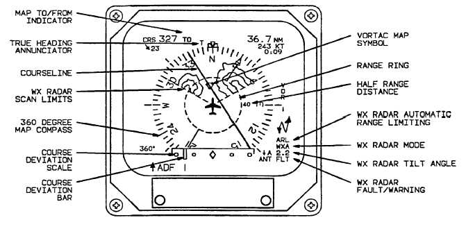
Figure 3A-15. EHSI 360° Map Symbol Definitions
b. EHSI Controls, Indicators, and Functions.
Refer to Figure 3A-16.
(1) Course/Desired Track Digital Display.
The
course/desired
track
digital
display
is
an
alphanumeric display located in the upper left comer of
the EHSI. It displays CRS followed by the selected
navigation course in degrees. The CRS knob on the
EFIS control panel rotates the course pointer about the
compass scale and sets the course/desired track
digital display.
(2) Drift Angle Indicator. The drift angle
pointer is a triangular pointer that is generated by the
GPS and rotates around the outside of the compass
scale. Referenced to the lubber line, the drift angle
pointer displays drift angle left or right of aircraft
heading. With respect to the compass scale, the drift
angle pointer displays actual ground track. Drift angle
pointer information is provided by the GPS and will be
displayed only when the GPS is selected as the
primary navigation source and valid information is
present. If the pointer information becomes invalid, it
will be removed from the display.
(3) Directional Gyro Mode Or Source. The
directional gyro mode or source annunciator located to
the left of the lubber line indicates whether heading
information is being supplied to the EFIS from
directional gyro number 1 or 2 (DG1 or DG2), or if the
system is operating in the free gyro mode (FDG).
(4) Lubber Line. Aircraft heading is read
from the compass card under the lubber line.
(5) Heading Marker. The heading marker is
positioned on the compass card by rotating the
heading select knob located on the EFIS control panel.
(6) Heading Miscompare Indicator. The
yellow double-ended heading miscompare arrow will
be displayed over HDG to the left of the lubber line on
the EHSI if heading 1, 2, and cross-side differ by more
than 6 up to 6 of bank and by more than 20 above
6 of bank. If bank information is not available the
heading miscompare will be displayed if heading
differs by more than 20. The heading miscompare
symbol will also be displayed if the failure warning
flags differ. Heading miscompare will not be
performed if sources are not all magnetic or all true.
(7) Primary Navigation Source Range (Or
Held DME Distance). The range display for the
primary navigation source or DME hold distance is
displayed in the upper right comer of the EHSI.
(8) Groundspeed or DME Hold Frequency.
Displays groundspeed to 999 KTS or DME hold
frequency.
(9) Time To Go. Displays time to station up
to 8:31 (H:MM universal format). Time to station is
displayed immediately below and at the same time as
groundspeed.


