TM 1-1510-223-10
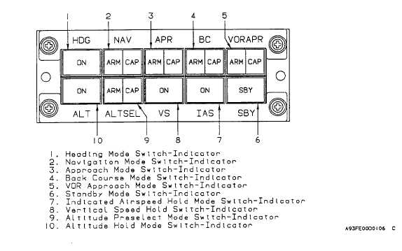
Figure 3-22. Flight Director Mode Selector
(1) Heading mode switch-indicator. Depressing
the heading mode switch-indicator, placarded HDG, will
illuminate the ON indicator on the face of the switch and
will command the flight control computer to follow the
inputs of the heading marker located on the heading dial
of the coupled EHSL
(2) Navigation
mode
switch-indicator.
Depressing
the
navigation
mode
switch-indicator,
placarded NAV, will cause the flight control computer to
arm, capture, and track the navigation signal (VOR, LOC,
TACAN, or LNAV) which has been selected as the
navigation source for the EFIS. When approach (APR)
has been selected, the navigation (NAV) select switch-
indicator will annunciate lateral tracking status.
(3) Approach mode switch-indicator. Depressing
the approach mode switch-indicator, placarded APR, will
select the appropriate gains to arm and capture the lateral
navigation signal for localizer (LOC) and vertical
navigation signals for the glideslope. Except for an ILS,
when approach is selected, the NAV switch will
annunciate the appropriate arm or capture condition
(4) Back
course
mode
switch-indicator.
Depressing the back course mode switch-indicator,
placarded BC, will command the flight control computer to
track the localizer back course, and will illuminate the
ARM or CAP indicators on the switch face as appropriate.
(5) VOR approach mode switch-indicator.
Depressing the VOR approach switch-indicator, placarded
VOR APR, will select the appropriate gains for capturing
and tracking a VOR during the approach phase of flight,
and will illuminate the ARM and CAPture indicators on the
switch face when appropriate.
(6) Standby mode switch-indicator. Depressing
the standby mode switch-indicator, placarded SBY, will
remove all the selected flight director modes, forcing the
command bars to be removed from the EADI, and will
illuminate the SBY indicator located on the switch face.
(7) Indicated airspeed hold mode switch indicator.
Depressing the indicated airspeed hold mode switch-
indicator, placarded IAS, will command the system to
maintain the current indicated airspeed or to allow a new
indicated airspeed to be selected with either the autopilot
pitch wheel or by using the touch control steering switch
on the control wheel. When operating in the IAS mode
the ON indicator located on the face of the switch will be
illuminated and the target airspeed will be displayed on
the EADI.
(8) Vertical speed hold mode switch-indicator.
Depressing the vertical speed hold mode switch-indicator,
placarded VS, will command the system to maintain the
3-46