TM 1-1510-223-10
3-34 Change 3
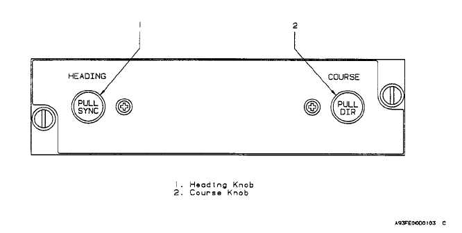
Figure 3-14. Flight Director Remote Heading/Course Control Panel
selected. The amber VAR annunciator indicates that
variable gain has been selected.
(24) Lightning sensor system mode annunciator.
The lightning strike sensor system mode annunciator
indicates the operating mode of the lightning sensor sys-
tem. Possible annunciations are LX, LX/F, LX/S, LX/T,
LX/H, LX/I, LX/C, LX/L, and LXMN. All annunciations are
green except LX/F and LXMN which are amber. These
mode annunciators are described in the lightning sensor
system paragraph in this chapter.
(25) Compass system synchronization annuncia-
tor. The compass synchronization system annunciator
indicates the state of the compass system in the slaved
mode. The bar represents commands to the compass
gyro to slew to the indicated direction (+ for increased
heading and 0 for decreased heading.) Compass syn-
chronization annunciation will be removed during the
compass free gyro mode. If the cross-side compass
display has been selected, the synchronization annun-
ciator will be removed.
c. EHSI Partial Compass Format (fig. 3-15). The
partial compass mode displays a 90-degree ardc of the
compass card. The following additional features are
available during partial compass operation:
(1) Range rings. Range rings are displayed to aid
in the use of radar returns and position of navaids. The
outer range ring is the compass card boundary and rep-
resents the selected range on the radar. Range annunci-
ation on the inner ring represents one-half the range
setting of the weather radar.
(2) Navaid position. Navaid position may be se-
lected for display during map mode. Source of navaid
position markers is selected and annunciated in conjunc-
tion with the associated bearing source and is color
coded.
(3) Weather. Weather radar information may be
displayed in the partial compass mode.
(4) Off scale arrow. When the heading marker is
rotated out of view (off scale) an arrow on the compass
arc is provided to indicate the shortest direction of the
heading marker.
d. EHSI Short Range Navigation (SRN) Map Mode
(fig. 3-16). Map mode is selected by depressing the
FULL/MAP pushbutton selector switch on the display
controller until the EHSI is in the MAP mode.
When the map mode has been selected, the following
will occur:


