TM 1-1510-223-10
Change 3 3-29
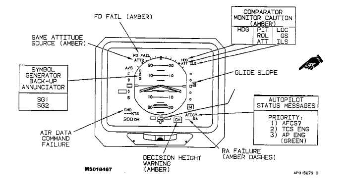
EXPANDED LOCALIZER OR
RATE OF TURN
Figure 3-10. EADI Caution Annunciators (Amber)
Heading selection
Glideslope deviation
Time-to-go
Heading and navigation source annunciators
Heading synchronization
(2) Partial compass display Weather radar
Lightning sensor system data
Navigation map
b. EHSI Controls, Indicators, and Functions (fig.
3-13).
(1) Course/desired track display. The course
(CRS)/desired track (DTRK) display provides a digital
readout of the course selected by the course pointer
(yellow) or the desired track when navigation with infor-
mation supplied by the INS. Course (CRS) or desired
track (DTRK) are displayed in white letters with the nu-
merical course displayed in yellow.
(2) Single-needle bearing pointer. The single-
needle bearing pointer (blue circle) indicates the relative
bearing to the selected navaid. The navigation source is
indicated by the single-needle pointer source annuncia-
tor. When the bearing pointer navigation source is invalid
or a localizer frequency has been chosen, the bearing
pointer will be removed from the display.
(3) Heading source annunciator. The heading
source annunciator will display MAG1 or MAG2 when
slaved or DG1 or DG2 when free, to show which gyro-
compass system is providing heading information to the
EHSI.
(4) Heading marker. The notched blue heading
marker is positioned on the heading dial by the respec-
tive heading selection knob on the remote instrument
controller panel, which is located on the pedestal exten-
sion (fig. 2-12). Once set to the desired heading, the
heading marker will maintain its position on the heading
dial. The difference between the heading marker and the
lubber line index is the amount of heading select error
applied to the flight director computer. In heading mode,
the EADI pitch and roll command cue will display the
proper bank commands to turn to and maintain this se-
lected heading. Pulling on the heading select knob (ped-
estal extension, fig. 2-12) will set the heading marker to
aircraft heading.
(5) Lubber line. Aircraft heading is read from the
heading dial under the lubber line.