TM 1-1510-218-10
3B-14
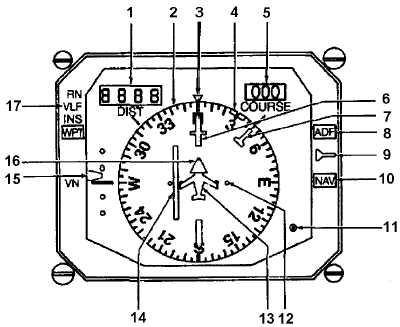
1. Distance Display
2. Rotating Heading Dial
3. Lubber Line
4. Heading Bug
5. COURSE Display
6. Course Pointer
7. Bearing Pointer
8. ADF Annunciator
9. Bearing Pointer Source Switch
10. NAV Annunciator
11. Compass Synchronization Annunciator
12. Course Deviation Dots
13. Aircraft Symbol
14. Course Deviation Bar
15. Glideslope Pointer/Scale
16. To/From Pointer
17. Navigation Source Annunciators
Figure 3B-6. Pilot's Horizontal Situation Indicator (HSI)
(11) Compass Synchronization Annunciator.
The compass synchronization annunciator consists of
a dot and X symbol display. When the compass
system is in the slaved mode, the display will oscillate
between the dot and X symbol, indicating the heading
dial is synchronized with a gyro stabilized magnetic
heading.
(12) Course
Deviation
Dots.
In
VOR
operation, each dot represents 5° deviation from the
centerline (+ 10°). In ILS operation, each dot
represents 1° deviation from the centerline.
(13) Miniature Aircraft Symbol. The fixed
miniature
aircraft
symbol
corresponds
to
the
longitudinal axis of the aircraft and lubber line
markings. The symbol shows aircraft position and
heading with respect to a radial course and the
rotating heading (azimuth) dial.
(14) Course Deviation Bar. The course
deviation bar represents the centerline of the selected
VOR or localizer course. The miniature aircraft symbol
pictorially shows actual aircraft position in relation to
this selected course.
(15) Glideslope Pointer/Scale. The glideslope
pointer displays glideslope deviation. The pointer is in
view only when tuned to a localizer frequency. If the
aircraft is below glideslope path, the pointer is
displayed upward on the scale. Each dot on the scale
represents approximately 0.4° displacement.
(16) To-From Pointer. The to-from pointers,
aligned on the course pointer, are located 180° apart.
One always points in the direction of the station, along
the selected VOR radial.
(17) Navigation Source Annunciators. Two
different annunciators display navigation data sources,
RN for area navigation and GPS.
The pilot’s HSI also has a HDG flag which
indicates a loss of heading information, a NAV flag
which indicates a loss of NAV 1 or unreliable GPS
navigational signal and a VERT flag which covers the
glideslope pointer when not receiving glideslope
information.


