TM 1-1510-218-10
3-84
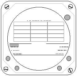
To place the item into one of the six positions on
the screen, press the PLACE button. This places the
data item in the upper left position in the legend area.
To move the item to another position, press the MOVE
button. Each additional press of the MOVE button
advances the item counterclockwise. Refer to Figure
3-120.
BFG
BRT
OFF
Navaid Setup
CANCEL
MOVE
ETE
GS
TRK
Brg
XTK
ETA
*N/A
*
Rng
ETA
MESA
XTR
MSA
GS
ETE
Brg
Trk
WPT
MVar
*
*
Time
Lat
LONG
*
SET
Figure 3-120. Navaid Setup – Move
To set the display position of a highlighted item,
press the SET button. This establishes the position of
the data item display on the weather screens. After
pressing the SET button, the highlight will return to the
next data item on the grid. To return the data item to
the grid without setting, press the CANCEL button.
This will return the data item highlight to the grid.
Since the data item was not set to the legend area,
any data item previously occupying the position will
remain there. To select additional data items, repeat
the sequence of NEXT to highlight the item, PLACE it
from the grid to the legend area, MOVE it to the
desired position on the legend area, and SET it. To
replace a data item previously set in position, follow
the same sequence. Pressing the SET button when a
highlighted data item is in an occupied legend position
causes the new item to replace the previous item.
To erase an item from the legend area, press
NEXT to highlight the blank space on the grid, PLACE
it to the legend area, MOVE it in the legend area to the
position to be erased, and SET it.
Press the EXIT button to return to the Options
Menu. Press MENU to return the Main Menu including
the weather options.
(7) Error Messages. Most common errors
and malfunctions are indicated on the display screen.
These
messages
enable
service
personnel
to
diagnose and correct the problem. If continued
operation is possible, a message to press any key to
continue operation will be displayed. When the
LORAN or GPS receiver fails to acquire a consistent
signal and is not certain of its position, the message
NAV FLAG will appear in place of the CDI.
Navigational data will not be displayed if the receiver
indicates a flag condition. In conditions where the
LORAN or GPS receiver determines its position error
to be greater than 1.7 nm, a W (warning) will appear
next to the affected data items.
3-10. TRANSPONDER SET (AN/APX-100).
a. Description.
The transponder system
receives, decodes, and responds to interrogations
from ATC radar to allow aircraft identification, altitude
reporting, position tracking, and emergency tracking.
The system receives a radar frequency of 1030 MHz
and transmits preset coded reply pulses on a radar
frequency of 1090 MHz at a minimum peak power of
200 watts. The range of the system is limited to line-
of-sight.
The transponder system consists of a combined
receiver/transmitter
control
panel,
Figure
3-121,
located on the pedestal extension; a pair of remote
switches, one on each control wheel; and two
antennas located on the underside and top of the
fuselage. The system is protected by a 3-ampere
circuit
breaker,
placarded
XPONDER
D2
or
TRANSPONDER C D1 , or XPONDER #2 IFF T
located on the right side of the circuit breaker panel,
Figure 2-16.
b. Controls/Indicators and Functions. Refer
to Figure 3-121.
(1) TEST / GO Indicator – Illumination
indicates successful completion of built-in-test (BIT).
(2) TEST / MON Indicator – Illumination
indicates unit has malfunctioned, or interrogation by a
ground station (MON).
(3) ANT Switch. Selects desired antenna for
signal output.
Place the TOP / BOT / DIV switch in the DIV
position during flight operations. Do not
use the TOP or BOT position. This does
not preclude using the TOP or BOT switch
position for ground–based system checks.
(a) TOP – Selects use of top antenna.
WARNING