TM 1-1510-218-10
3–85
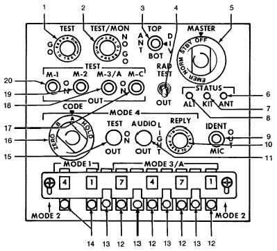
1. TEST / GO Indicator
2. TEST/MON NO GO Indicator
3. ANT Switch
4. RAD TEST / OUT Switch
5. MASTER Control
6. STATUS ANT Indicator
7. STATUS KIT Indicator
8. STATUS ALT Indicator
9. IDENT / OUT / MIC Switch
10. MODE 4 REPLY Indicator
11. MODE 4 AUDIO / LIGHT–OUT Switch
12. MODE 3/A Code Selectors
13. MODE 2 Code Selectors
14. MODE 1 Code Selectors
15. MODE 4 TEST / ON / OUT Switch
16. MODE 4 CODE Control
17. M–C TEST Switch
18. M–3/A TEST Switch
19. M–2 TEST Switch
20. M–1 TEST Switch
Figure 3-121. Transponder Control Panel (AN/APX-100)
(b) DIV – Selects diversity operation
using both antennas.
(c) BOT
–
Selects
use
of
bottom
antenna.
(4) RAD TEST OUT Switch. Enables an
appropriately equipped transponder to reply test mode
interrogations from an AN/UPM-92 or similar test set.
(5) MASTER
Control.
Selects
system
operating mode.
(a) OFF – Turns set off.
(b) STBY – Places set in warmup
(standby) condition. Red NO-GO light is ON in
standby position.
(c) NORM – Operates set at normal
sensitivity.
(d) EMER – Transmits emergency reply
code.
(6) STATUS ANT Indicator – Illumination
indicates the BIT or MON failure is due to high VSWR
in antenna.
(7) STATUS KIT Indicator – Illumination
indicates the BIT or MON failure is due to external
computer.
(8) STATUS ALT Indicator – Illumination
indicates the BIT or MON failure is due to Altitude
Digitizer.


