
TB 43-0149
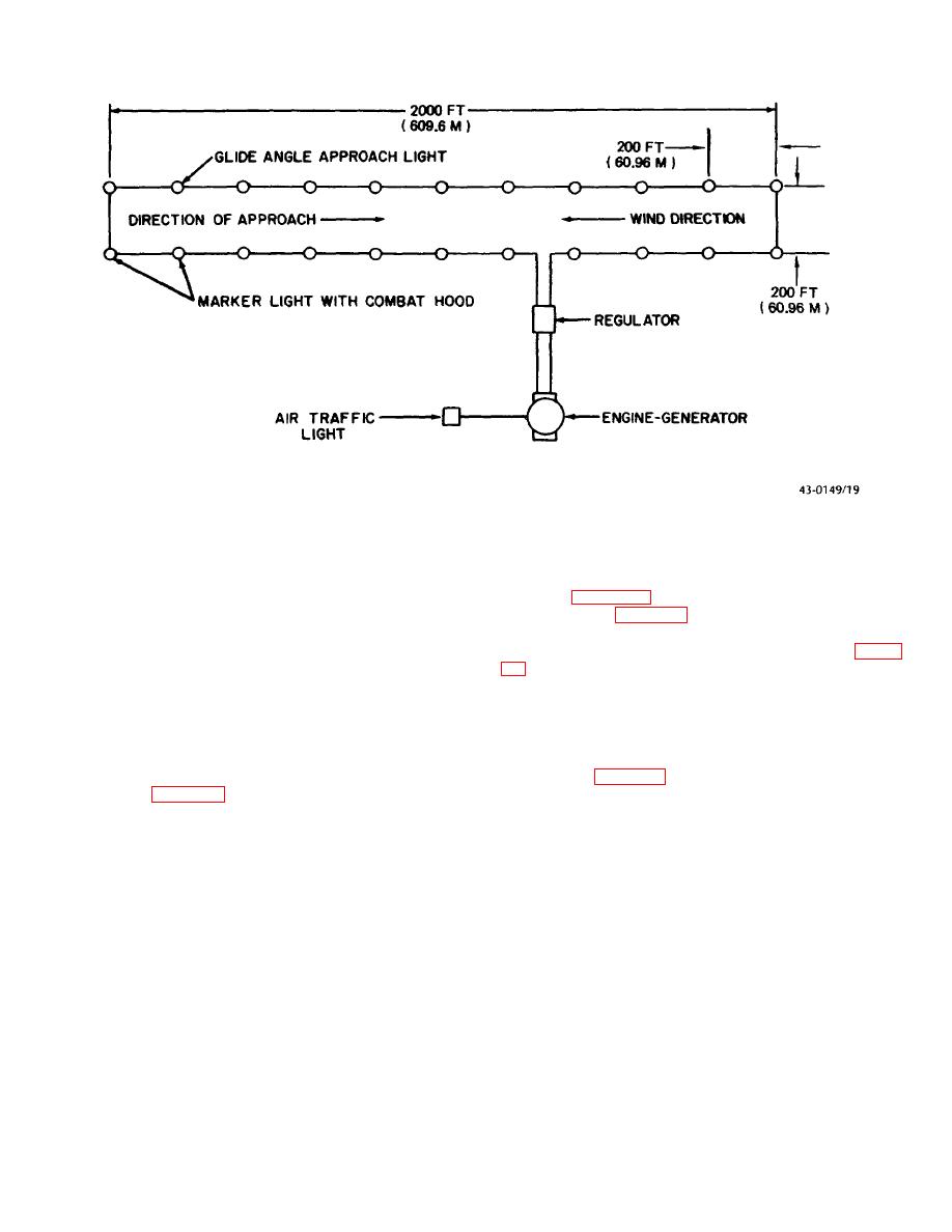
Figure 19. Circuit layout for airfield runway in a combat area.
nector, the circuit may be completed with a male
(1) The 200-foot (60.96 meter) power cable are laid
adapter (figure 21); if 2 male ends meet, a female
along each edge of runway to permit the runway lights to
adapter is used (figure 22). After the generator has been
be mounted at 200-foot (60.96 meter) intervals and
sited, a single conductor cable is run from each of the
directly opposite each other across the runway. At the
two nearest marker lights to the current regulator (figure
ends of the runway, either 50-foot (15.24 meter) or 200-
foot (60.96 meter cables may be used to connect the
been connected, stakes are driven at the proper
threshold lights
locations and the lighting fixtures and glide angle
approach light are placed, assembled, connected, and
(2) After the cables have been laid out, step down
leveled. Lighting fixtures are installed by first placing the
transformers for marker lights and for the glide angle
separated bottom half of the mounting adapter on a
indicator light are placed at their required locations. The
driven stake (figure 23).
primary leads of the tranformers are connected to the
power cables (figure 20). If it is necessary to connect a
transformer lea and a power cable, each of which has a
female con
14
