TM 55-4920-401-13&P
should indicate resistance specified for aircraft being
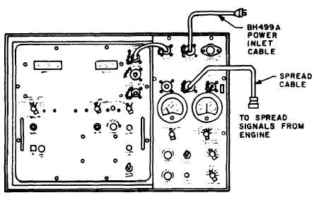
2-6. Temperature Spread Test. The temperature
checked.
spread test checks combustion chamber flame prop-
(10) If either insulation resistance reading is not
agation during engine run. During this test, the
within tolerance, locate source of leakage and repair.
temperature of each thermocouple in the engine can
be read independently with the tester. The average
NOTE
temperature may also be read at any time during
the test. Refer to figure 2-8 and proceed as follows:
Healing of EGT harness of 200 degrees F for
a. Turn FUNCTION SELECT, STD DAY, and
1 hour, letting cool to ambient temperature,
MASTER POWER switches to OFF position.
will increase insulation resistance.
b. Connect spread cable to SPREAD CABLE re-
ceptacles on tester and to spread connector on en-
( 1 1 ) T u r n F U N C T I O N S E L E C T a n d
gine (if required, use spread adapter).
MASTER POWER switches to OFF position before
c. Turn FUNCTION SELECT switch to SPREAD
removing cables from tester and aircraft.
position.
Figure 2-8. Temperature Spread Teat Setup.
d. Turn TEMPERATURE switch to OPERATE
position and MASTER POWER switch to ON posi-
tion.
e. Start engine and stablize rpm.
f. Turn SPREAD switch successively to each
thermocouple position and note reading of each
t h e r m o c o u p l e o n t e s t e r T E M P i n d i c a t o r .
Temperature gradient (spread) between engine
t h e r m o c o u p l e s s h o u l d n o t e x c e e d a l l o w a b l e
technical manual limits.
g. Turn FUNCTION SELECT and MASTER
POWER switches to OFF position before removing
cables from tester and aircraft.
2-5 Engine Trim Check. During operation, the
relationship between rpm, temperature, and fuel
flow is critical. Therefore, the tester, which
measures rpm to ± 0.1 percent and temperature to
± 2 degrees C, is used to measure these engine
functions. The portable trimmer portion may be
removed and placed in the cockpit during trimming.
If aircraft has D’Arsonval type indicator(s) and it is
desirable to check indicator accuracy during engine
trim, a switch box (fig. 2-9), which is an accessory to
the tester, must be used. Refer to figure 2-10 or 2-11
and proceed as follows:
a. Turn FUNCTION SELECT. STD DAY, and
MASTER POWER switches to OFF position and T/
C INPUT switch to CHECK CABLE position.
NOTE
If trimmer section is to be removed
and placed in cockpit, remove power
i n t e r c o n n e c t c a b l e f r o m t e s t e r .
Connect power cable and power cable
adapter to POWER INTERCONNECT
c o n n e c t o r a n d t o p o w e r s o u r c e
i d e n t i f i e d
a t t h e P O W E R
I N T E R C O N N E C T c o n n e c t o r .
Disregard reference to FUNCTION
S E L E C T a n d T / C I N P U T s w i t c h
positions.
Change
4
2-9


