TM 55-4920-401-13&P
i.
Turn FUNCTION SELECT, STD DAY, and
MASTER POWER switches to OFF position before
removing cables from tester and aircraft.
2-7. RPM Indicator Check.
In the rpm indicator
check, engine rpm is read simultaneously on the tester and
the cockpit indicators during engine run. The two readings
arc compared to determine the rpm system error. Refer to
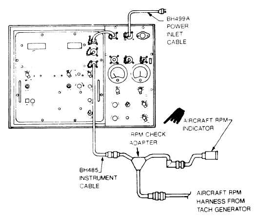
figure 2-12 and proceed as follows:
a. Turn FUNCTION SELECT, STD DAY, and
MASTER POWER switches to OFF position.
b. Connect BH485 instrument cable to RPM INPUT
INSTRUMENT CABLE connector on tester and to proper
rpm check adapter.
NOTE
Refer to table 1-14 for appropriate RPM
check adapter.
c.
Disconnect aircraft rpm circuit either at rpm indica-
tor or tachometer generator (depending on type of rpm
check adapter used) and insert rpm check adapter as shown
in figure 2-12.
d. Turn FUNCTION SELECT switch to TRIM
position and MASTER SWITCH to on.
e. Turn RPM SWITCH to either N1 or N2 position.
f. With aircraft engine running, monitor % rpm on
rpm indicator of tester and compare with cockpit indicator.
NOTE
1% RPM difference is allowed. If a difference
exists, refer to appropriate TM for testing of
the indicator and tachometer generator.
g. Turn FUNCTION SELECT, STD DAY, and
MASTER POWER switches to OFF position before
removing cables from tester and aircraft.
Figure 2-12. RPM Indicator Check Setup
2-12
Change 6


