TM 55-4920-401-13&P
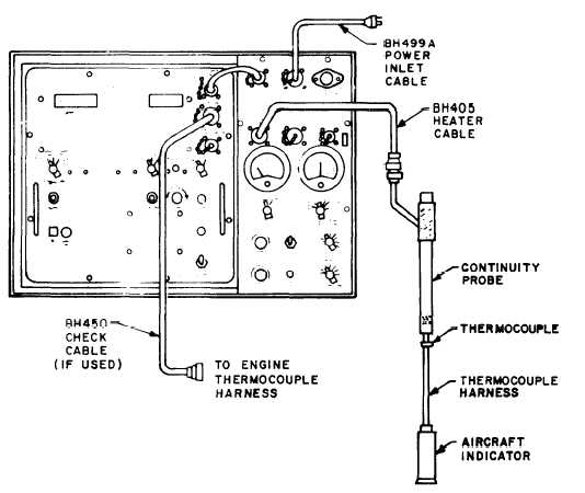
Figure 2-1.
Thermocouple System Continuity Check Setup.
CABLE position, TEMP indicator should indicate
temperature rise as each thermocouple junction is heated.
(7) Three continuity possibilities exist:
(a) Continuity O.K. Proceed to paragraph
(b) Continuity on some, but not all, thermo-
couples. Check thermocouples and harness wiring.
(c) No continuity. Make a rapid check of all
connectors and associated wiring and if no mal-
function is detected, make harness check (para a),
indicator check (paras b or c) and insulation check
(para e) until open circuit point is detected. After
discontinuity is detected and repaired, perform ac-
curacy test in paragraph b.
b. Temperature System Accuracy Check. T h e
accuracy check is used to test the entire aircraft
temperature system by heating all engine thermo-
couples and comparing the temperature displayed
on the aircraft temperature indicator with the
heater probe temperature displayed on the tester
TEMP indicator. Refer to figure 2-2 and proceed as
follows:
NOTE
To check an engine not installed in an
aircraft, follow the procedure listed
below with the following exception.
The check cable (and check cable
adapter, if required) must be con-
nected to the engine harness junction
connector and to the CHECK CABLE
receptacle. The temperature of the en-
gine thermocouples is read on the
tester TEMP indicator by switching
the T/C INPUT switch to CHECK
CABLE position.
(1) Turn FUNCTION SELECT, STD DAY,
and MASTER POWER switches to OFF position
a n d t u r n P R O B E C O N T R O L f u l l y c o u n t e r -
clockwise.
(2) Connect BH405 heater cable to HEATER
CABLE receptacle on tester and connect junction
box to heater cable.
(3) Connect as many heater probes having the
correct part number to the junction box as there are
engine thermocouples.
2-2
Change 4