TM 55-4920-401-13&P
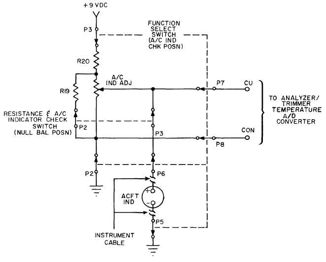
Figure 1-19. Aircraft Indicator Check Circuit for Null-Balanc Indicators.
(c) Heater Probe Temperature Cir-
cuit. The averaged heater probe temperature sig-
nal of the precision thermocouples in the heater
probes is applied through the heater cable (fig. 1-
16) to the HEATER CABLE receptacle. This signal
is selected by the T/C INPUT switch and applied to
the “heater probe” contacts of decks 7 and 8 of the
FUNCTION SELECT switch.
(d) Trim Circuit. The averaged egt signal
from the engine thermocouple harness is applied
through the check cable (fig. 1-16) to the CHECK
CABLE receptacle on the trimmer. This signal is se-
lected by the T/C INPUT switch and applied to the
“trim” contacts of decks 7 and 8 of the FUNCTION
SELECT switch.
1-18
(e) Temperature Indicator Calibration
Circuit. The temperature indicator calibration sig-
nal generator is on the calibrator board (fig. 1-16) in
the trimmer. A2 and A3 on this board form an iso-
lated power source that generates approximately 22
vdc at C14. This power source drives A4 which pro-
vides a source of constant current for 9 vdc zener
diode CR11. The 9 vdc from CR11 powers compen-
sator MOD-1, which is identical to the compensator
in the temperature indicator. Since the compen-
sator outputs are series opposed, the thermocouple
effect is cancelled. R3 on the calibrator board ad-
justs the calibration signal to an equivalent 600° C.
(f) Heater Probe Temperature Set Cir-
cuit. The heater probe temperature set circuit (fig.