TM 55-4920-401-13&P
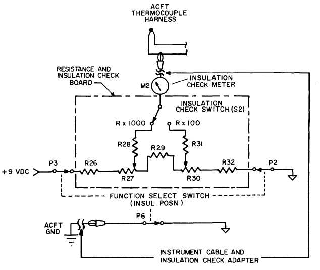
Figure 1-23. Insulation Check Circuit (Simplified Schematic)
board.
(9) Resistance Check Circuit. This circuit
(fig. 1-24), located in the probe controller, is used to
check and adjust the resistance of the aircraft ther-
mocouple circuit. It consists of a Wheatstone bridge
with the RESISTANCE CHECK meter serving as
the galvanometers. One leg of the bridge contains a
precision wirewound resistor that is selected with
the RESISTANCE % A/C INDICATOR CHECK
switch. The aircraft thermocouple circuit (less the
indicator) is placed in the other leg of the bridge.
The aircraft resistance spool is then adjusted until
the galvanometer is balanced.
(10) Power Supplies and Power Distribu-
tion. Primary line voltage (115 vat. 50-400 Hz) is
applied to the POWER INPUT receptacle on the
probe controller. The voltage is applied through the
interconnect cable and the MASTER POWER
switch to the primary windings of T1 in the trim-
mer. There are five secondary windings on trans-
former T1 (fig. 1-25). All secondary windings are
center-tapped. Only switch positions that switch
power are shown in figure 1-25.
(a) Twenty-Eight VDC Supply. This sup-
ply consists of the circuitry of CR9, CR10, and Q10-
Q12 on the switch-power board. It is referenced to
the -15 vdc supply. The 28 vdc supply excites the
STD DAY lamp and its control circuit. It is also
switched by the FUNCTION SELECT switch to the
1-23


