TM 55-4920-401-13&P
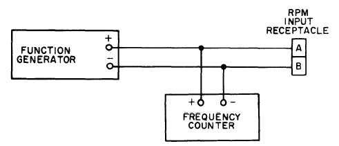
Figure 4-2. % RPM Indicator Test Setup.
c Standard Day Circuit Accuracy Check.
(1) Make testsetups of figures 4-1 and 4-2.
(2) T u r n T E M P E R A T U R E s w i t c h t o
OPERATE, RPM switch to N1, STD DAY switch to
ON, FUNCTION SELECT switch to TRIM, and
place T/C INPUT switch in CHECK CABLE
position.
(3) Using 16.398 mvdc and 63 Hz as inputs
(table 4-2), set AMB TEMP potentiometer to
different settings in table 4-2 and check readings of
temperature and % rpm displays against readings in
table.
(4) Readings of the TEMP ºC display shall not
differ more than + 3-1/2º and readings of the %
RPM display shall not differ more than + 0.5% rpm
from the corresponding values in the table.
d. Heater Probe Check and
Control Circuit Accuracy Check.
CAUTION
Heater Probe
Never add cold probes to a tester that
is regulating other probes at elevated
temperature. To do so could cause
overheating of hot probes, since probe
c o n t r o l l e r o p e r a t e s o n a v e r a g e
temperature.
NOTE
If less than 8 heater probes are used,
the correlation between the PROBE
CONTROL setting and the heater
probe temperature may exceed +40 C.
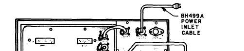
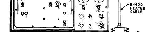
(1) Make test setup of figure 4-3.
Figure 4-3. Test Setup of Heater Probe Control Circuit.
4-3