
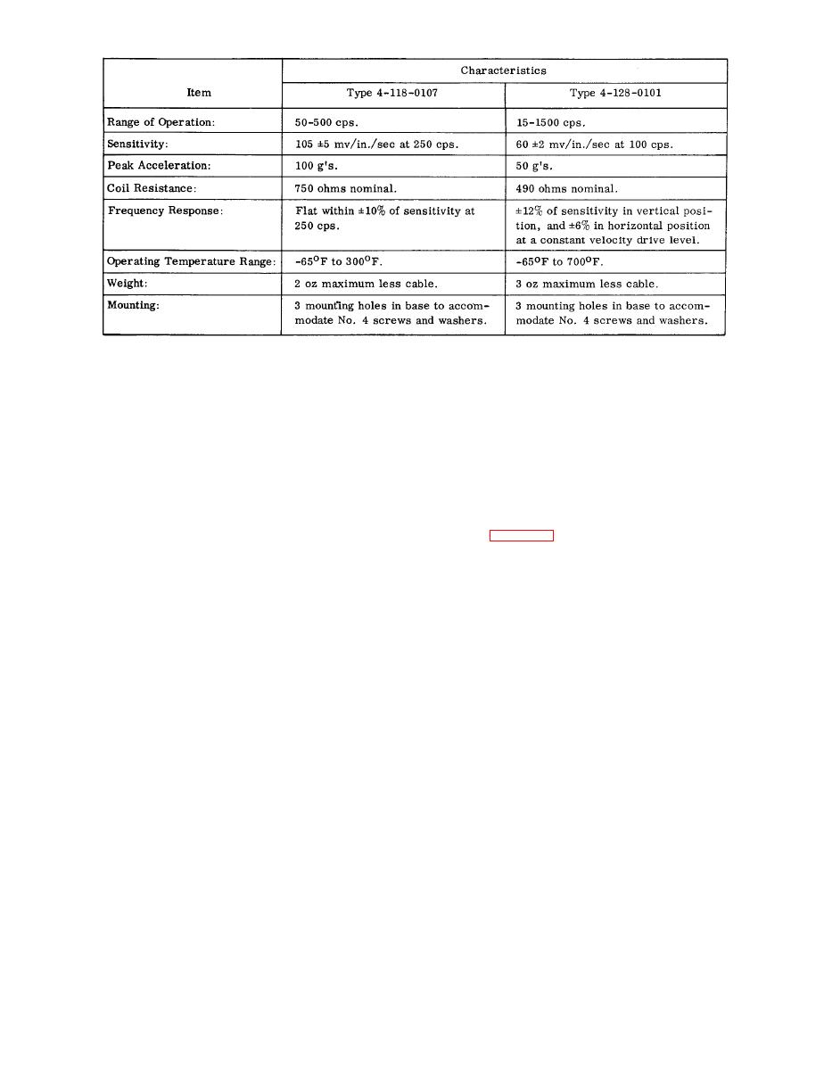
Technical Characteristics, Vibration Transducer Types 4-118-0107 and 4-128-0101
1-24. APPLICATIONS.
1 - 2 0 . RECORDING EQUIPMENT. The vibration
meter output may be permanently recorded for de-
tailed waveform study by connecting a galvanometers
1-25. The vibration test kit measures engine vibra-
tion at specified operating speeds of the N1 and N2
of a recording oscillograph to the GALV. connector
on the rear panel of the vibration meter. The vibra-
systems. Vibration transducers attached to adapters
tion meter readings are not affected by the use of this
mounted on the engine, transmit electrical impulses
connector. Full scale on the meter corresponds to
through cables to the vibration meter. The vibration
approximately 555 microampers rms in the galva-
meter indicates the total amount of engine movement
nometer circuit. Galvanometers with resistance of
(peak-to-peak displacement) in mils. Meter indica-
100 ohms or less should be used.
tions are recorded on an Engine Vibration Test Data
Sheet (see figures 1-9 through 1-12). The recorded
1-21. OSCILLOSCOPES. A cathode-ray oscilloscope
figures are compared with the figures given on the
with an input impedance of 0.5 megohm or greater
data sheet for maximum permissible engine vibra-
may be connected to the SCOPE connector on the front
tion. If these maximum figures are exceeded, the
panel of the vibration meter. This permits simul-
cause of the excessive vibration must be found and
taneous viewing of the amplitude and velocity indica-
corrected before the engine can be accepted for
tions on the vibration meter and waveforms on the
unrestricted flight.
1-26. Vibration engine tests are performed by third
echelon maintenance activities. Measurements are
1-22. EXTERNAL METER. An external meter may be
taken after removal and installation of the first stage
used for remote indication of velocity of displacement.
turbine rotor assembly, the engine combustion sec-
This meter should have a full scale value of 500 micro-
tion, the engine exhaust section, or when excessive
ampere dc and a resistance of 200 ohms or less.
engine vibration is suspected.
1-23. CONTROL AND WARNING DEVICES. A wide
1-27. PREPARATION FOR USE.
variety of special circuits may be devised for auto-
matic control of equipment, or for warning operators
1-28. Paragraphs 1-29 through 1-30 are installation
of unsafe vibrations of any predetermined magnitude.
procedures and preliminary checkout procedures for
Any of the three vibration meter output circuits may
the vibration test kit.
be used for this purpose, provided the impedances in-
troduced are within the specified ranges. Devices con-
1-29. PRELIMINARY SYSTEM CHECKOUT. Prior
nected to the ac outlets should have pure resistive
to installation of mounting adapters and transducers
inputs. All three output connections may be used
on the engine, check the system out to be sure that
simultaneously.
all parts are functional, as follows:
