TM 55-1510-221-10
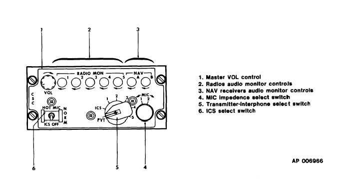
Figure 3-1. Audio Control Panel (Typical Pilot, Copilot)
tion of interface circuit with best impedence match
to microphone used.
(a.) The impedance of MIC 1 posi-
tion is 5 Ohms.
(b.)
The impedance of MIC 2 posi-
tion is 150 Ohms.
(5.)
Transmitter-interphone selector switch.
Connects microphone and headset to selected radio
transmitter or interphone line routing received
audio to headset. Bypasses control of respective
receiver audio switch.
(a.) PVT. Position not used.
intercom.
(b.) ICS. Activates pilot-to-copilot
(c.) No.1. Permits audio reception
from VHF-AM No. 1 transceiver. Routes key and
microphone signals to VHF-AM No. 1 transceiver.
(d.) No.2. Permits audio reception
from VHF/AM/FM transceiver. Routes key and
microphone signals to VHF/AM/FM transceiver.
(e.) No.3. Permits audio reception
from No. 1 UHF transceiver. Routes key and mic
signals to No. 1 UHF transceiver.
(f.) No.4. Permits audio reception
from HF or VOW transceivers. Routes key or micro-
phone signals to transceiver.
(g.) No.5 Permits audio reception
from No. 2 UHF (BU VOW). Routes key and and
microphone signals to transceiver.
(6.) ICS select switch. Controls activation
of microphones.
(a.) HOT MIC. Admits speech to
interphone system without need to key selected
microphone.
(b.) NORM. Blocks speech from
interphone system unless selected microphone is
keyed.
(c.) ICS OFF. Deactivates inter-
phone system.
c. Normal Operation.
(1.) Turn-on procedure: Both audio con-
trol panels are activated when electrical power is
applied to aircraft.
3-3


