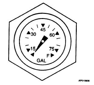
Figure 2-17. Auxiliary Fuel Tank Mechanical
Fuel Gage
The fuel system incorporates a fuel line shutoff
valve mounted on each engine firewall. The firewall
shutoff
valves
close
automatically
when
the
fire
extinguisher T-handles on the instrument panel are pulled
out. The firewall shutoff valves receive electrical power
from the main buses and also from the hot battery bus
which is connected directly to the battery. The valves are
protected by circuit breakers placarded FIREWALL
VALVE No.1 or No.2 on the overhead circuit breaker
panel (fig. 2-27), and FIREWALL SHUTOFF No.1 or
No.2 on the hot battery bus circuit breaker board.
g.
Fuel Tank Sump Drains. A sump drain wrench is
provided in the aircraft loose tools to simplify draining a
small amount of fuel from the sump drain.
(1)
There are five sump drains and one filter
drain in each wing (table 2-3).
(2)
An additional drain for the extended range
fuel system line extends through the bottom of the wing
center section adjacent to the fuselage. Anytime the
extended range system is in use, a part of the preflight
inspection would consist of draining a small amount of
fuel from this drain to check for fuel contamination.
Whenever the extended range system is removed from
the aircraft and the fuel line is capped off in the fuselage,
the remaining fuel in the line shall be drained.
h.
Fuel Drain Collector System. Each engine is
provided with a fuel drain collector system to return fuel
dumped from the engine during clearing and shutdown
operations back into its respective nacelle tank. The
system draws power from the No.4 feeder bus. Fuel
transfer is completely automatic. Fuel from the engine
flow divider drains into a collector tank mounted below the
aft engine accessory section. An internal float switch
actuates an electric scavenger pump which delivers the
fuel to the fuel purge line just aft of the fuel purge shutoff
valve. A check valve in the line prevents the backflow of
fuel during engine purging. The circuit breaker for both
pumps is located in the fuel section of the overhead
circuit breaker panel; placarded SCAVENGER PUMP. A
vent line, plumbed from the top of the collector tank, is
routed through an inline flame arrestor and then
downward to a drain manifold on the underside of the
nacelle.
i.
Fuel Vent System. Each fuel system is vented
through two ram vents located on the underside of the
wing adjacent to the nacelle. To prevent icing of the vent
system, one vent is recessed into the wing and the
backup vent
Table 2-3. Fuel Sump Drain Locations
NUMBER
DRAIN
LOCATION
1
Leading Edge Tank
Outboard of nacelle, underside of wing
1
Integral Tank
Underside of wing, forward of aileron
1
Firewall fuel filter
Underside of cowling forward of firewall
1
Sump Strainer
Bottom center of nacelle forward of wheel well
1
Gravity feed line
Aft of wheel well
1
Auxiliary Tank
At wing root, just forward of the flap
2-34