TM 55-1510-220-10
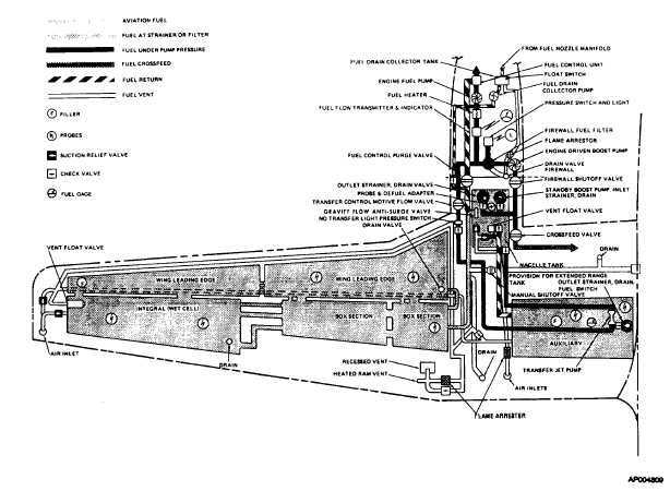
Figure 2-13. Fuel System Schematic
pressure, due to failure of an engine driven boost pump
will illuminate the MASTER WARNING lights on the
glareshield and will illuminate the No. 1 FUEL PRESS or
No.2 FUEL PRESS on the warning annunciator panel.
Turning ON the STANDBY PUMP will extinguish the
FUEL PRESS lights. The MASTER WARNING lights
must be manually cleared.
NOTE
Both standby pump switches shall
(3)
Fuel
transfer
control
switches.
Two
switches on the fuel management panel (fig. 214),
placarded AUX TRANSFER OVERRIDE AUTO control
operation of the fuel transfer pumps. During normal
operation both switches are in AUTO which allows the
system to be automatically actuated by fuel flow to the
engine. If either transfer system fails to operate, the fault
condition is indicated by two illuminated MASTER
CAUTION lights on the glareshield and a steadily
illuminated yellow No.1 NO FUEL XFR or No.2 NO FUEL
XFR light on the caution annunciator panel.
(4)
Fuel crossfeed switch. The fuel crossfeed
valve is controlled by a 3-position switch (fig. 2-14),
located on the fuel management panel, placarded
CROSSFEED OFF. Under normal flight conditions the
switch is left in the OFF position. During emergency
single engine operation, it may become necessary to
supply fuel to the operative engine from the fuel system
on the opposite side. The crossfeed system is placarded
for fuel selection with a simplified diagram on the
overhead fuel control panel. Place the standby fuel pump
switches in the off position when
2-30