TM 55-1510-219-10
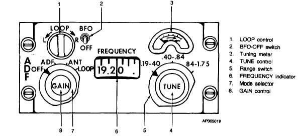
Figure 3-16. ADF Control Panel (DF-203)
Tuning meter
Indicates relative strength of re-
ceived signals.
TUNE control
Selects operating frequency.
Range switch
Selects operating frequency
band.
FREQUENCY
Indicates selected frequency.
indicator
Mode selector
Selects operating mode.
OFF
Turns set off.
ADF
Permits automatic direction
finding or homing operation.
ANT
Permits reception using sense
antenna.
LOOP
Permits audio-null homing and
manual direction finding opera-
tions.
GAIN control
Adjusts volume of received sig-
nal.
(2)
Switches - audio panel (fig. 3-1).
CONTROL
FUNCTION
NAV B volume
NAV B volume control applies
control
ADF audio to aircraft audio sys-
tem.
(3)
Switches - radio panel (fig. 3-2).
CONTROL
FUNCTION
FILTER V-OFF
Selects whether voice filter will
switch
be used with ADF audio.
FILTER R-OFF
Selects whether range filter will
switch
be used with ADF audio.
c.
Operation.
(1)
To operate set as automatic direction
finder.
1. Mode selector - ADF.
2. BFO-OFF switch - BFO.
3. Range switch - Select.
4. TUNE control - Rotate for maximum
reading on tuning meter and zero
BFO beat.
5. GAIN control - As required.
6. Double needle switches (RMI, fig. 3-
9) - As required.
3-30


