TM 55-1510-219-10
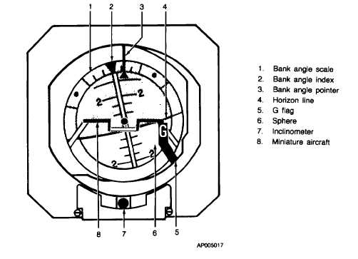
Figure 3-14. Copilot's Gyro Horizon Indicator (GH-14)
applied to various aircraft systems through pilot and
copilot COMPASS No. 1/No. 2 switches (fig. 2-28).
There are no circuit breakers for the gyro magnetic
compass systems. The circuits are protected by the 2-
ampere F2 and F6 fuses on the No. 1 junction box.
b.
Vertical Gyro. A vertical gyro provides line-of
sight stabilization to the weather radar and roll and pitch
information to the autopilot. No controls are required or
provided for operation of the vertical gyro system. The
circuit is protected by the 3ampere F22 fuse in the No.
1 junction box.
c.
Controls and Indicators.
CONTROL/
FUNCTION
INDICATOR
Pilot's
Selects desired source for mag-
COMPASS No.
netic heading information to dis-
1/No. 2 switch
play on pilot's HSI and copilot's
RMI.
No. 1
Selects compass system No. 1
for display.
No. 2
Selects compass system No. 2
for display.
Copilot's
Selects desired source for mag-
COMPASS No.
netic heading information to dis-
1/No. 2 switch
play on copilot's HSI and pilot's
RMI.
No. 1
Selects compass system No. 1
for display.
No. 2
Selects compass system No. 2
for display.
COMPASS
Provides visual indication of
SLAVE
system synchronization opera-
annunciator
tion.
GYRO SLAVE/
Selects system mode of opera-
FREE switch
tion.
SLAVE
Selects slaved mode of opera-
tion.
FREE
Selects free mode of operation.
INCREASE/
Provides manual fast synchroni-
DECREASE
zation of the system.
switch
INCREASE
Causes gyro heading output to
decrease (move in counter-
clockwise direction).
DECREASE
Causes gyro heading output to
increase (move in clockwise di-
rection).
3-25


