TM 55-1510-219-10
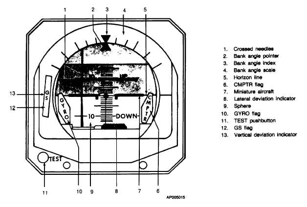
Figure 3-12. Horizon Reference Indicator (329B-9A)
Horizon line
Affixed to sphere, remains paral-
lel to the earth's horizon at all
times.
Miniature
Indicates attitude of aircraft
aircraft with respect to the earth's hori-
zon.
Sphere
Remains oriented with the
earth's axis at all times.
GYRO flag
Presence indicates loss of power
to, or low rotational speed of,
vertical gyro.
CMPTR flag
Presence indicates a malfunction
within the autopilot computer.
LOC flag
Presence indicates that localizer
information is not available or
not reliable.
NOTE
When flying coupled to the INS
system, the CMPTR flag will be in
view
anytime
the
steering
information
is
invalid
or
a
malfunction exists in the autopilot
computer.
GS flag
Presence indicates glideslope in-
formation is not being presented
on indicator.
TEST
When pressed, display indicates
pushbutton an additional 10° nose up, 20°
right roll and the GYRO flag is
visible.
3-20. PILOT'S TURN AND SLIP INDICATOR.
a.
Description. The pilot's turn and slip indicator
(fig. 3-13) is used to provide automatic yaw damping
information to the autopilot in addition to performing the
functions of a turn -and slip indicator. It is protected by
the 5-ampere PILOT TURN & SLIP circuit breaker
located on the overhead circuit breaker panel (fig 2-26).
b.
Controls and Indicators.
INDICATOR
FUNCTION
Turn rate
Deflects to indicate rate of turn.
indicator
Two-minute turn
Fixed markers indicate two-
marks
minute turn rate when covered
by turn rate indicator.
GYRO warning
Presence indicates loss of power
to instrument.
3-23


