TM 55-1510-219-10
needle switch is in the VOR/
TACAN position.
VOR 1
Selects VOR 1 bearing signals
for display.
TACAN
Selects TACAN bearing signal
for display.
(2) RMI (fig. 2-28).
CONTROL/
FUNCTION
INDICATOR
Double needle
Indicates bearing selected by
pointer
double needle switch.
Compass card
Indicates aircraft heading at top
of dial.
Heading index
Reference point for aircraft
heading.
Warning flag
Indicates loss of compass signal.
Double needle
Selects desired signal to be dis-
switch
played by double needle pointer.
ADF position
Selects ADF bearing informa-
tion.
VOR position
Selects VOR 2 bearing informa-
tion.
Single needle
Indicates bearing selected by sin-
pointer
gle needle switch.
Single needle
Selects desired signal to be dis-
switch
played on single needle pointer.
INS position
Selects the bearing to waypoint
position.
VOR/TACAN
Selects VOR 1 or TACAN bear-
position
ing information.
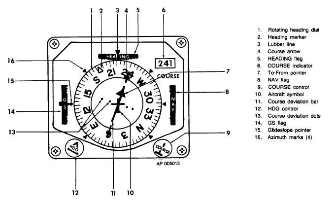
3-18. HORIZONTAL SITUATION INDICATORS.
a. Description. The pilot and copilot have separate
HSI
instruments
on
respective
instrument
panel
sections. Each HSI indicator combines displays to
provide a map-like presentation of the aircraft position.
Each
indicator
displays
aircraft
heading,
course
deviation, and glideslope data. The pilot's HSI allows
the desired course and autopilot input to be set
manually. Either HSI will display back localizer sensing,
when the front course is selected and back course is
flown. Course deviation is supplied to the HSI by the
VOR 1 or VOR 2 systems, the TACAN (Tactical Air
Navigation System), or the INS (Inertial Navigation
System). Glideslope data is supplied by the VOR 1 or
VOR 2 systems. The HSI displays warning flags when
the VOR/LOC, INS, TACAN, heading or glideslope
signals are lost or become unreliable.
Figure 3-10. Pilot's Horizontal Situation Indicator (331A-8G)
3-19


