T.O. 1-1A-9
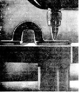
Figure 8-5. Standard Pyramid Diamond Indentor
d.
A foot pedal, which when depressed, returns the
cam, drum and weight to their original positions, thus
cocking the mechanism and preparing the instrument for
another test.
e.
A tripper, which supports the beam during the
return of the cam, weight and drum. The tripper also
released the lever for load applications.
f.
A medium-power compound microscope for
measuring the indentation across the diagonal of a
square.
8-17. Making The Vickers Test. The test is applied as
follows (See figure 8-4):
1.
Prepare the sample by smooth grinding or
polishing to remove all scratches and variations that
may affect the readability of the indentation.
2.
Place the test piece (6) on the testing table (5)
and turn the table elevating wheel (1) until the indentor
(7) fails to contact the metal being tested.
CAUTION
Sudden contact of the indentor
and the material under test should
be avoided to prevent possible
injury to the diamond point.
3.
Depress the load trip level (8) applying the load.
The duration of the load application is fixed by the
manufacturers at from 10 to 30 seconds, the time being
determined by the rate at which oil is allowed to bleed
out of the dashpot. The load is fully applied, the
indentor is automatically released.
4.
Elevate the indentor by turning the wheel.
Lower the testing table by reversing the table elevating
wheel.
5.
Swing the microscope (10) into place until
locked.
6.
View the impression of the indentation in the
form of a square in the field shown by the
eyepiece.
7.
Bring the left corner of the impression, by
means of the centering screws (13) to a point where it
touches the left hand fixed knife edge. Adjust the right
hand movable knife edge by means of the micrometric
screw connected to the counter until it touches the right
hand corner of the impression. The counter (15) will
then show an ocular reading which is transposed to the
Vickers pyramid numeral by use of correlation tables
accompanying the tester.
8.
Where specified hardness limits are desired the
third knife edge is used. This is moved by means of
special screws to correspond to the smaller dimension
or maximum hardness, while the micrometer-controlled
knife edge is adjusted to correspond to the minimum
hardness or larger dimension. When the settings of the
second and third knife edges are made, it is only
necessary when taking readings to set the fixed knife
edge to the left hand corner of the impression in the
usual way. If the right hand corner of the impression
appears between the second and third knife edges, the
material has the proper hardness for the range desired.
8-18. SHORE SCLEROSCOPE HARDNESS TEST.
The Shore scleroscope is not a precision instrument as
the others discussed in preceding paragraphs. It is used
to give approximate values for comparative hardness
readings. Testing hardness with the scleroscope
consists of dropping a diamond tipped hammer upon the
test specimen from a definite height and measuring the
rebound produced. In one type of tester, the height of
the rebound must be measured directly on the scale of
the machine, while on another the amount is indicated
on a dial.
8-19. The Scleroscope Tester. The tester (Figure 8-6)
consists of the following major parts:
a.
A base, provided with leveling screws,
and a clamping arrangement to hold the sample to be
tested.
8-7


