TM 1-7010-386-12&P
OPERATION UNDER USUAL CONDITIONS
0005 00
5.
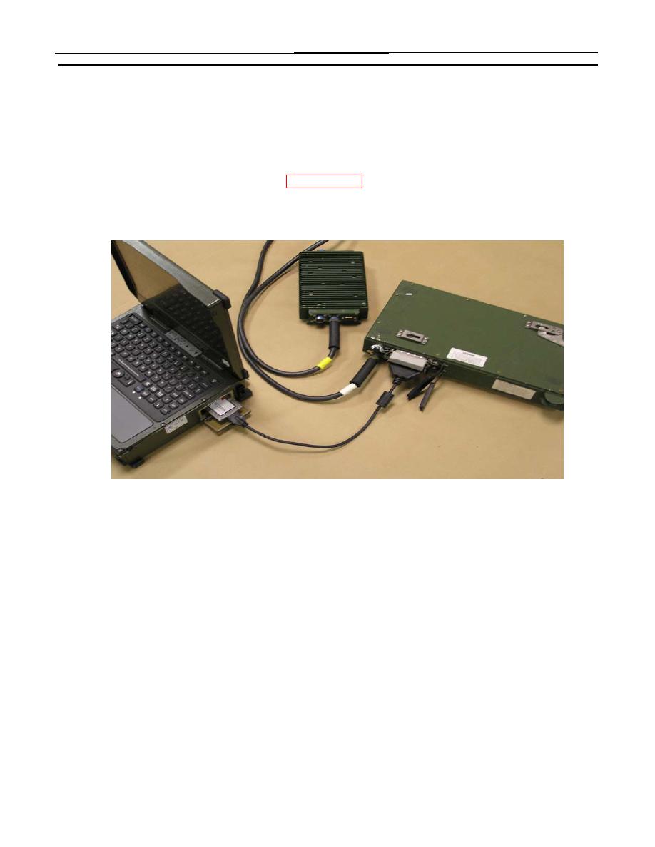
Connect the (large) male end of the SCSI PCMCIA cable (4) to J2 of the Transfer Unit (1).
6. Connect the (small) male end to the SCS1 PCMCIA cable (4) to the slot on the back of the Slim SCSI
1480B PCMCIA card (5).
7. Rotate the PCMCIA access door fasteners clockwise to unlatch the door of the AMPS PCU. Insert the
CardBus side of the Slim SCSI 1480B PCMCIA Card (5) into the AMPS PCU following the installation
procedures "Using the PCMCIA Cards", WP 0005 00-11.
Completed SDTMR connection
Connecting Rugged Printer Assembly
Connect the external power source for the Rugged Printer Assembly by connecting the Printer Power Cable from
connector J4 of the External Power Module to the 3-pin power connector on the back of the printer assembly.
Data transfer between the PCU and the Rugged Printer Assembly is through a 25 pin parallel cable. Connect the
parallel cable from the Parallel Port on the back of the PCU to the parallel connector on the back of the printer.
Connecting Single Channel Ground/Airborne Radio System (SINCGARS)
Data transfer between the PCU and a Single Channel Ground/Airborne Radio System (SINCGARS) occurs
through the Portable Computer Improved Data Modem (PC-IDM) Card. The PC-IDM Card uses the PCMCIA
bay on the side of the PCU.
AMPS and Radio Configuration for Messaging
1. AMPS PCIDM Configuration (first time only)
Insert PCIDM card in top PCMCIA slot.
Right-click My Network Neighborhood and select Properties
Right-click Local Area Connection 2 (PCMCIA\Innovative) and select Properties
0005 00-7


