TM 1-1510-225-10
3B-27
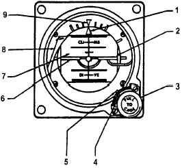
(2) Standby Attitude Reference Indicator
Controls and Indexes T3 OSA . Refer to Figure
3B-14.
(a) Roll Pointer – Indicates vertical in any
roll attitude.
(b) Horizon
Line
– Indicates earth's
horizon relative to aircraft pitch attitude.
(c) Caging / Pitch-Trim Knob – Pulled to
cage the indicator and rotated to adjust the miniature
aircraft attitude.
(d) Trim
Pointer
–
Indicates
trim
displacement.
1. Roll Pointer
2. Horizon Line
3. Caging/Pitch-Trim Knob
4. Trim Pointer
5. Pitch-Trim Scale
6. Miniature Aircraft
7. Drum
8. Power Warning Flag
9. Roll Index
Figure 3B-14. Standby Attitude Reference
Indicator T3 OSA
(e) Pitch-Trim
Scale
–
Measures
displacement of miniature aircraft.
(f) Miniature
Aircraft
–
Represents
aircraft nose and wings. Indicates roll and pitch
attitude relative to the horizon. Adjustable through
pitch trim knob for varying pitch attitudes.
(g) Drum – Directly linked to the spin
motor to provide direct reading of aircraft movement in
roll and pitch. Marked each 5 in pitch. Black area of
drum indicates dive and blue or gray area indicates
climb.
(h) Power Warning Flag – In view,
indicates power off, caged condition, open motor
winding, or loss of power. Retracted, indicates normal
operation.
(i) Roll Index – Rotates with aircraft to
provide measurement of angular displacement by the
roll pointer during maneuvers.
3B-18. AUTOMATIC FLIGHT CONTROL SYSTEM.
a. Description. The Automatic Flight Control
System is a completely integrated autopilot/flight
director/ air data system that has a full complement of
horizontal and vertical flight guidance modes. These
include all radio guidance modes, and air data oriented
vertical modes.
When engaged and coupled to the flight director
commands, the system will control the aircraft using
the same commands displayed on the electronic
attitude director indicator. When engaged and
uncoupled from the flight director commands, manual
pitch and roll commands may be inserted using the
Touch Control Steering (TCS) or the pitch wheel and
turn knob.
When the autopilot is coupled, the flight director
instruments
act
as
a
means
to
monitor
the
performance of the autopilot. When the autopilot is not
engaged, the same modes of operation are available
for flight director only. The pilot maneuvers the aircraft
to satisfy the flight director commands, as does the
autopilot when it is engaged.
NOTE
The
autopilot
will
disengage
when
transferring between the pilot and copilot
flight directors.
b. Autopilot Flight Director Transfer Panel. A
panel, containing an alternate action autopilot and
flight director transfer switch, placarded AP FD 1 / AP
FD 2, is located on the pedestal extension. This
switch is used to select which autopilot flight director
computer controls the aircraft flight servos. If AP FD 2
is selected, the annunciators, placarded AP FLT DIR
NO. 2, located above the copilot’s airspeed indicator,
and the annunciator, placarded AP FLT DIR NO. 1,
located above the pilot’s altimeter, will illuminate to
alert both pilots that the No. 2 autopilot flight director
computer is controlling the aircraft. If the AP FD 1 is
selected, only the annunciator labeled AP FD 1 above
the pilot’s altimeter will illuminate.