TM 1-1510-224-10
setting. The accelerate-go distance (flaps up) would
exceed the available runway length, so a flaps-approach
takeoff must be calculated if it is desired to allow for the
accelerate-go distance (which is not a regulatory
requirement, but a recommended practice).
i.
Takeoff Path One Engine Inoperative. Graphs
are provided to estimate the horizontal distance required
to reach a height of 1500 feet, or the minimum climb
gradient required to clear an obstacle along the takeoff
flight path. If clearance of obstacles beyond the runway
is required, these results may restrict takeoff weight
accordingly.
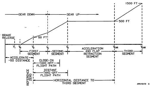
The takeoff distance extends from brake release
to reference zero, which is the point at which the aircraft
is 50 feet above the runway. The net takeoff flight path
begins at liftoff and consists of the following segments:
1.
The first segment climb extends from liftoff
to the point where the landing gear
completes the retraction cycle. The
airspeed is maintained at V2.
2.
The second segment climb begins at the
end of the first segment and extends to
500 feet above the runway. The airspeed
during the second segment is V2.
3.
The
acceleration
and
flap
retraction
segment consists of an acceleration from
V2 to VE,R at a constant height of 500
feet. If a flaps approach takeoff was
made, begin flap retraction at VENR.
4.
The third segment climb begins when one
engine-inoperative climb speed is reached
and flaps are fully retracted at 500 feet,
and extends to 1500 feet above the
runway. Airspeed is maintained at VENR
during this segment.
j.
Tak eoff Path Profile (Flaps Approach, One
Engine Inoperative). The following examples illustrate
the use of the flaps-approach takeoff path graphs. Enter
the graphs at 15C FAT, 3499 feet pressure altitude,
16,000 pounds takeoff weight, 1.9% downhill runway
gradient, and a 10-knot headwind component.
(1)
Example 1 close-in obstacle clearance:
given:
Obstacle Height Above Aircraft at Brake Release..... 88
feet
Obstacle Distance from Brake Release ..........16,294
feet
1.
The obstacle horizontal distance from
Figure 7-1. Takeoff Path Profile - One Engine Inoperative
7-12


