TM 1-1510-224-10
circuits on vertical gyros, and servo command outputs.
Servo command outputs from a computed servo model
in all three axes are compared to actual commands. If
the difference between commands exceeds a certain
threshold
value,
the
flight
control
computer
is
disconnected from the servos. Normal flight control
computer functions are computed based on the vertical
and directional gyros selected with the respective EFIS
display controllers.
b.
Flight
Control
Computer/Autopilot
Mode
Annunciation.
Flight
control
computer/autopilot
operating modes are annunciated on the flight director
mode selector and on each electronic attitude director
indicator (EADI). The flight director command bars, on
the coupled side's EADI, reflect the selected mode. The
navigation sensor used for the selected modes is chosen
with the display controller (DC-811) and annunciated on
the EHSI.
c.
Autopilot
Self-Disconnection
Fault
Messages. The pilot can investigate the cause of an
inflight autopilot disconnection by depressing the SBY
button on the flight director mode selector for more than
5 seconds. The altitude preselector display will be
disconnected from the digital air data computer and
connected to the autopilot. A numerical fault code will
appear on the altitude preselector display. Table 3-4
provides an explanation of fault codes. Subsequent
pushes on the SBY switch on the flight director mode
selector will yield additional fault codes or dashes, which
indicate the end of the error code log. When the dashes
appear in the display, the altitude preselector display will
again be reconnected to the digital air data computer.
Fault messages are displayed as a letter code followed
by a three digit number. Ignore the last digit of the
number, which will be a zero.
If the autopilot was disconnected as a result of
the fault, depressing the AP DISC button on the control
wheel will allow the autopilot to be re-engaged, provided
the failure no longer exists.
d.
Digital Flight Control System Performance/
Operating Limits. Table 3-5 contains the digital flight
control system performance and operating limits.
e.
Yaw Damper. The yaw damper computer
provides basic yaw damper functions with or without the
autopilot.
When
the
autopilot
is
engaged
turn
coordination is active. Yaw damper mode is active when
either the YD or AP ENGAGE button on the autopilot
controller is selected.
f.
Rudder Boost. The yaw damper computer
also provides rudder assist (boost) in the event of an
engine failure. The amount of assist provided is
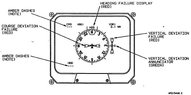
NOTE:
IN THE EVENT OF HEADING FAILURE. THE COURSE SCALE AND RED X WILL NOT
BE DISPLAYED AND THE CRS AND HDG READOUTS WILL INDICATE AMBER DASHES.
Figure 3-19. EHSI Failure Annunciators (Red)
3-40