TM 1-1520-218-10
3C-195
Section IV. RADAR AND TRANSPONDER
3C-27. WEATHER RADAR (KWX-58) SYSTEM T1 .
a. Description. The KWX-58 color weather
radar not only displays in-flight weather, but also
permits incorporation of the KGR-358 radar graphics
unit. The color weather radar is used to detect
significant en route weather formations to preclude
undesirable penetration of heavy weather and its
usually associated turbulence. The weather radar
system provides a 320 nm display, with a 250 nm
weather avoidance range plus weather penetration
advantages. With the radar graphics unit in the NAV
mode, navigation information is integrated with the
weat her display. The phased array antenna (flat
plate), located in the nose of the aircraft, is fully
stabilized to compensate for aircraft pitch and roll. The
antenna provides a full 90° scan angle, ± 12° tilt, and a
3.75 microsecond pulse width in both weather and
ground mapping modes.
(1) Extended Sensitivity Time Control (STC)
increases the displayed intensity of storms outside the
normal STC range. Extended STC relates the storm
intensity to its distance and assigns a corresponding
color. As a result, the display presents a more
accurate picture of storm intensity.
(2) Weather systems are displayed as four
colors, depicting rainfall intensity overlaid with range
rings. Bearing marks at dead ahead and 20° on either
side aid the pilot in judging the bearing of storms and
necessary heading changes.
(3) With radar graphics interfaced, a circle
mode may be activated by pressing the page button
located
on
the
radar
graphics
control
panel.
Functional operation in this mode is the same as in the
standard display mode and is available in both
weather and SBY modes. The range information is
displayed in the upper right corner and represents the
outer ring. The inside ring represents half the
displayed distance. The off screen pointer is replaced
by an RMI BUG annunciation placed on the outer ring
in the direction of the active waypoint and color coded
to each navigation system. Position of the aircraft is
indicated by the green airplane symbol in the center of
the screen.
(4) Indicator brightness is adjustable to
accommodate varying ambient light conditions while
automatically maintaining equal brightness between
the four display colors. The system is protected
through
a
5-ampere
circuit
breaker,
placarded
RADAR, located on the overhead circuit breaker
panel, Figure 2-16.
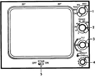
b. Controls and Functions. Refer to Figure
3C-144.
(1) Mode Selector Control Knob. The mode
selector knob is used to turn the system on/off, and
select SBY, TEST, WX, WXT, and MAP positions.
(a) SBY. In SBY mode, the display is
blanked and transmitter circuits are disabled with the
magnetron heater remaining on.
1. Mode Selector Control Knob
2. RANGE Selector Control Knob
3. TILT Control Knob
4. BRIGHT / GAIN / MAX Control Knob
5. OFF / STAB / ON Switch
Figure 3C-144. Weather Radar Control Indicator T1
(b) TEST. When placed in the TEST
mode, all circuitry is activated, except the transmitter.
All weather colors will display for verification in the
TEST mode as well as the WX, WXT, and MAP
modes.
(c) WX. The WX mode is the normal
weather mode with green for light, yellow for
moderate, red for heavy, and magenta for extremely
heavy precipitation.
(d) WXT. The WXT mode is used to
alert the pilot of weather that is beyond the displayed
range. Only returns of significant intensity between 83
and 320 nm are displayed with a white arc at the
approximate azimuth of the storm. A yellow T on a red
background will appear in the upper left corner of the


