TM 1-1510-218-10
3C-39
Table 3C-11. Heading Reference Indicator Values
HEADING SWITCH
SELECTION
ACTIVE FREE / SLAVE
SWITCH
FREE / SLAVE
SELECTION
HEADING REFERENCE
INDICATOR DISPLAYED
All on Compass 1
Pilot
Free
DG1 (amber)
Slave
MAG1 (amber)
All on Compass 2
Copilot
Free
DG2 (amber)
Slave
MAG2 (amber)
Normal
On-side
Free
DG (white)
Slave
Blank
3C-21. NAVIGATION RECEIVERS (KNR-634A).
a. Description. Two VOR localizer / glideslope/
marker beacon navigation receivers (KNR634A T1 ,
KNR-634 T2 ) and a TACAN/DME unit (KTU-709) are
controlled by two control units (KFS-579A and KFS-
564A) mounted in the instrument panel.
The NAV receivers receive and interpret VOR
range and LOC signals in the frequency range of
108.00 to 117.95 MHz, glideslope signals in the
frequency range of 329.15 to 335.00 MHz, and 75 Hz
marker beacon signals. In addition, the KFS-579A #1
NAV/TAC control tunes the KTU -709 TACAN/DME
system to all 252 TACAN channels. The NAV
receivers are powered through two 2-ampere circuit
breakers, placarded NAV #1 and #2, located on the
overhead circuit breaker panel, Figure 2-16.
b. NAV/TAC
Control
Unit
(KFS-579A)
Controls, Indicators, and Functions. Refer to
Figure 3C-17.
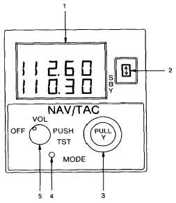
(1) Frequency Display. Liquid crystal digital
readouts provide a continuous display of both the
active frequency, or TACAN channel, and standby
frequency or TACAN channel (bottom line, placarded
SBY) when the system is in the frequency mode.
Display brightness is controlled by a switch, placarded
VHF / NAV / ADF, located right of the altitude alert on
the instrument panel.
(2) Frequency
Transfer
Switch.
The
frequency transfer switch is a momentary push-button
switch, placarded with a two-headed vertical arrow,
located to the right of the digital display.
1. Frequency Display
2. Frequency Transfer Switch
3. Tuning Knobs
4. MODE Switch
5. OFF / VOL / PUSH TST Control
Figure 3C-17. NAV/TAC Control Unit (KFS-579A)
(a) Standby Entry Mode. Pressing the
frequency transfer switch with the unit in the standby
entry mode causes the frequency or TACAN channel
displayed in the active (upper) digital display to
interchange with the frequency or TACAN channel
shown in the lower (standby) digital display.
(b) Active Entry Mode. While the unit is
in the standby entry mode, pressing the transfer switch
for longer than 2 seconds will cause the unit to enter
the active entry mode. While in the active entry mode,
momentarily pressing the transfer switch will return the
unit to the standby entry mode.