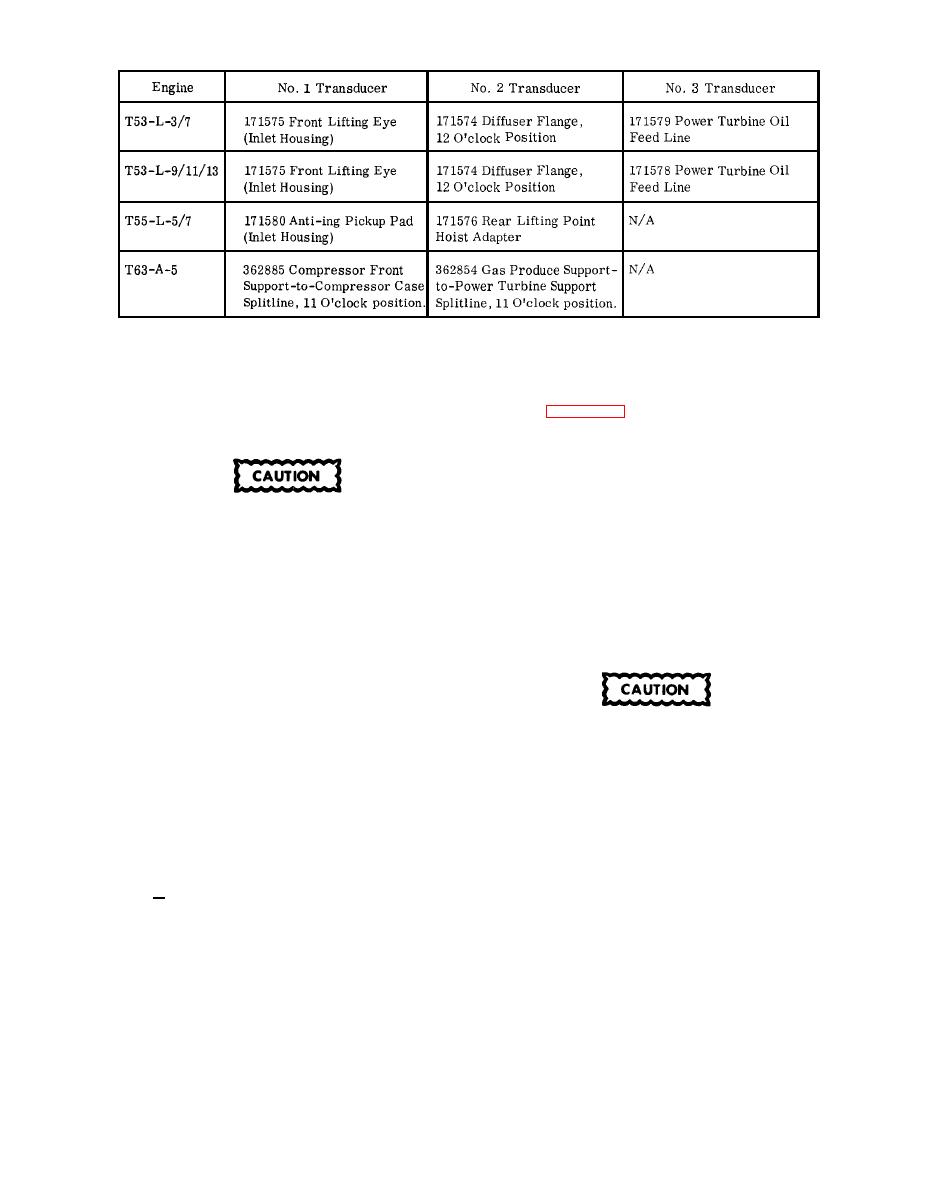
Location of Vibration Transducer Adapters on T53, T55, and T63 Series Engines
e. While the meter is warming up, lay out the
a. Install the proper adapters at the proper loca-
cables and transducers.
tions on the engine, removing engine bolts as neces-
sary. See figures 1-13 and 1-14 for the adapters and
f. Connect the transducer and cable for each chan-
cables to use for a particular engine, and figures
nel to the proper CHANNEL receptacle at the rear of
1-15 through 1-18 for proper location of adapters on
the meter.
the engine.
b. Secure each transducer to its adapter with three
4-40 screws and suitable lockwashers. Be sure to
Handle vibration transducers with care, acci-
tighten screws securely.
dental dropping or jarring may permanently
damage or decrease the accuracy of the unit.
c . Connect the proper cable assembly to each
transducer.
g. Set the meter IN PUT NETWORK selector to OUT.
NOTE
h. Set the CHANNEL selector to 1.
Identify adapters and cable connections with
numbers or colors to make certain the trans-
i. Set the RANGE selector to 5.
ducers will be connected to the proper vibra-
tion meter CHANNEL receptacles.
j. Shake the transducer connected to CHANNEL 1
by hand while observing the vibration meter. The
indicator should jog, or show a slight movement.
To prevent damage to the equipment, secure the
NOTE
cable assemblies to the engine and airframe
with tape or cord. Leave enough slack in the
If the indicator does not move, check the condi-
cables to prevent undue strain, on the trans-
tion of the transducer, connectors, cable, and
ducers and connections. Avoid kinks and sharp
vibration meter receptacle. Interchange com-
bends in cable assemblies. Avoid conditions
ponents until the defective unit is found. Re-
which would cause cables to deteriorate from
place or repair the defective component.
heat or abrasion.
k. Set the CHANNEL selector to the applicable
d. Secure vibration meter with bungee cord, or
number and, using the same procedures outlined in
other suitable means, to a cushioned, protected loca-
step j , check operation of each of the remaining
tion in the airframe.
transducers.
NOTE
procedure outlined below for installation of the
When testing engines installed in fixed wing
adapters and transducers onto the engine, and for
aircraft, the vibration meter may be placed on
interconnecting the cables.
a secure stand on the ground, if desired.


