
TM 55-4920-221-14
1.
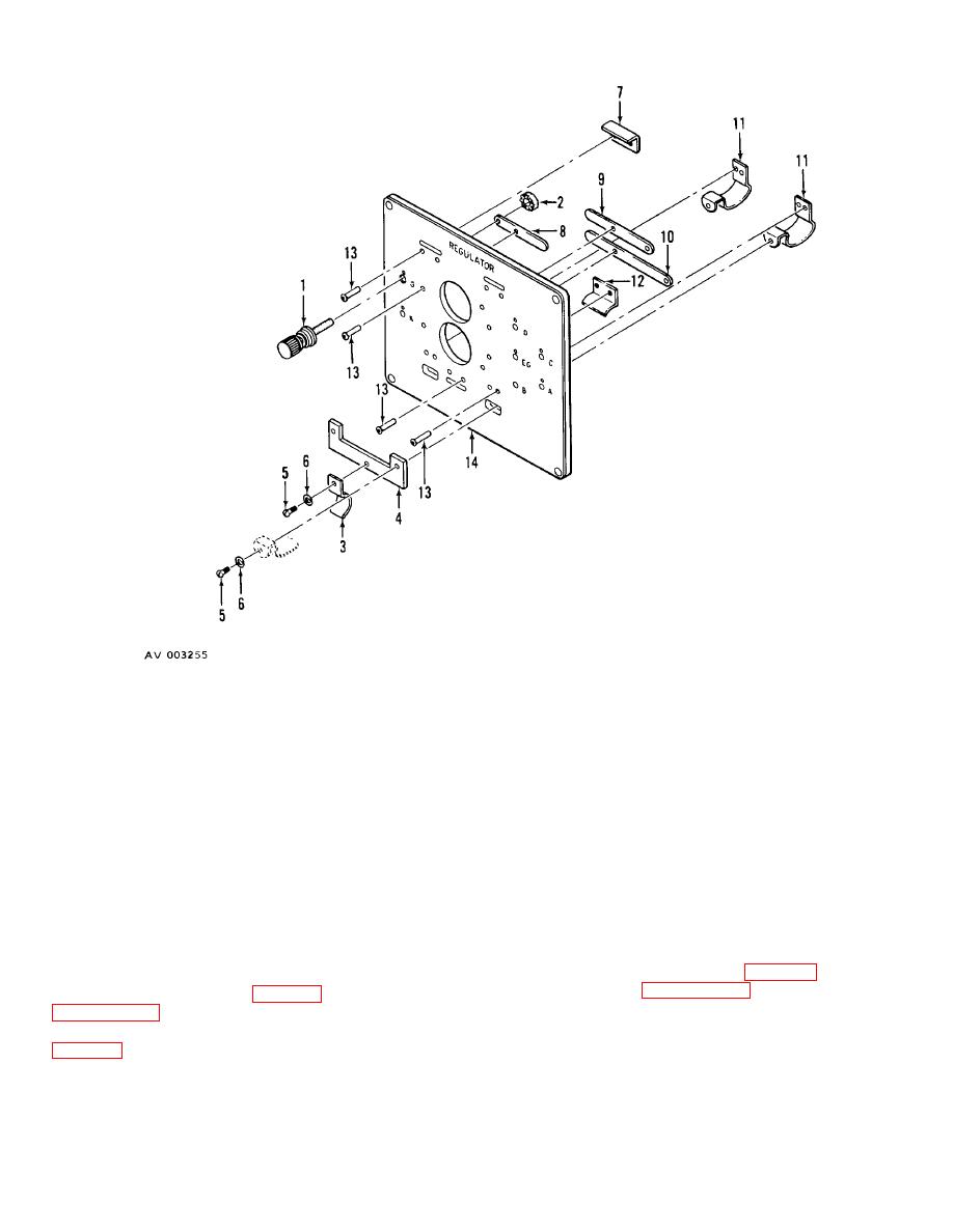
Binding post
6.
Lockwasher
11.
Clip
2.
Nut
7.
Bracket
12.
Bracket
3.
Clip
8.
Contact blade
13.
Rivet
4.
Bar
9.
Contact blade
14.
Mounting pad
5.
Screw
10.
Contact blade
Figure 15. Voltage Regulator Mounting Pad, Exploded View.
two screws (17) and nuts (18).
b. Cleaning and Inspection.
(5) Attach shunts (10, 13, and 14) on bus
(1) Clean parts with dry cleaning solvent P-D-
bars (19, 27, 28, and 29) with four screws (15), two
680 and dry thoroughly.
screws (11), and nuts (12).
(2) Inspect shunts and bus bars for cracks,
(6) Connect leads to shunts and bus bars.
breaks, corrosion, and damaged threads.
(3) Inspect threaded parts for worn or
129. BINDING POSTS.
damaged condition.
a. Removal.
c. Installation.
(1) Remove bus bar (27, figure 12) and shunt
(1) Position bus bar (20) in control panel and
(10) as described in paragraph 128.
attach relay bus bar (30, figure 7), as described in
(2) Remove binding post (32) and one
paragraph 115e(4).
insulating washer (34) from front of control panel, and
(2) Attach bus bars (16, 26, 27, 28, and 29,
one insulating washer from rear of panel.
(3) Remove thumb knob, and lug clearance
(3) Secure bus bars (20 and 26) with the
washer (30) from binding post.
screw (21) and nut (22).
(4) Secure bus bar (19) to bus bars (16) with
45
