
TM 55-4920-221-14
wattmeter range selector (44) inside control panel with
two upper screws (45) and nuts (47).
(4) Attach handle (71) on range selector with
setscrew.
(5) Install current transformer and shunt
assembly (paragraph 122d).
(6) Install T1 variable control (paragraph
117c(9)).
124. VOLTMETER PHASE SELECTOR AND DC
VOLTMETER CIRCUIT SELECTOR SWITCHES.
a. Removal.
(1) Tag and disconnect leads from terminals
on voltmeter phase selector (52, figure 12).
(2) Remove knob (51) and special nut from
shaft of voltmeter phase selector and remove selector
from rear of control panel.
(3) Remove resistors (paragraph 127a) and
remove dc voltmeter circuit selector (53), see (1) and (2)
above.
b. Cleaning, Inspection, and Repair.
(1) Clean parts with a cloth dampened in dry
cleaning solvent, P-D-680 and dry thoroughly.
(2) Inspect voltmeter phase selector and dc
voltmeter circuit selector for cracked or damaged case,
weak or broken spring, sticking or binding contacts, and
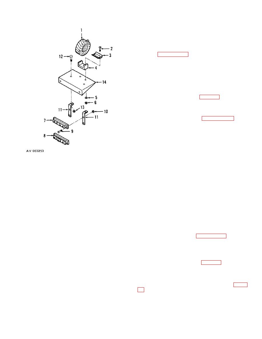
1.
Transformer
8.
Shunt
damaged terminals.
2.
Screw
9.
Screw
(3) Inspect threaded parts for worn or
3.
Clamping strip
10.
Nut
damaged condition.
4.
Channel
11.
Bracket
(4) Repair damaged -threads by chasing,
5.
Lockwasher
12.
Screw
when practical.
6.
Nut
13.
Nut
7.
Shunt
14.
Plate
c. Installation.
(1) Attach voltmeter phase selector (52) to
Figure 13. Current Transformer and Shunt,
the front of panel with special nut.
Exploded View.
(2) Install knob (51) with set screw.
(3) Connect leads to terminals on voltmeter
b. Cleaning, Inspection, and Repair.
phase selector, as tagged in a above.
(1) Clean parts with cloth dampened in dry
(4) Install dc voltmeter circuit selector (53) in
cleaning solvent, P-D-680 and dry thoroughly.
a similar manner.
(2) Inspect range selector for cracked or
(5) Install resistors (paragraph 127e).
damaged case, weak or broken spring, sticking or
binding contacts, and damaged terminals.
125. PHASE SEQUENCE INDICATOR.
(3) Inspect threaded parts for worn or
a. Removal.
damaged conditions.
(1) Tag and disconnect leads from terminals
(4) Repair damage threads by chasing when
on phase sequence indicator (54, figure 12).
practical.
(2) Remove phase sequence indicator (54)
c. Installation.
from front of control panel by removing four screws (55).
(1) Attach nameplate (48) on front of control
b. Disassembly.
panel with two screws (49) and nuts (50).
(1) Remove six resistors (1, 2, and 3, figure
(2) Insert four screws (45) through nameplate
and control panel and slide spacer (46) onto screws
tagging leads.
protruding inside control panel.
(2) Remove pilot light assembly (6) from front
(3) Attach single-phase ammeter and
of panel (12) by removing special nut and flat washer.
42
