TM 55-4920-221-14
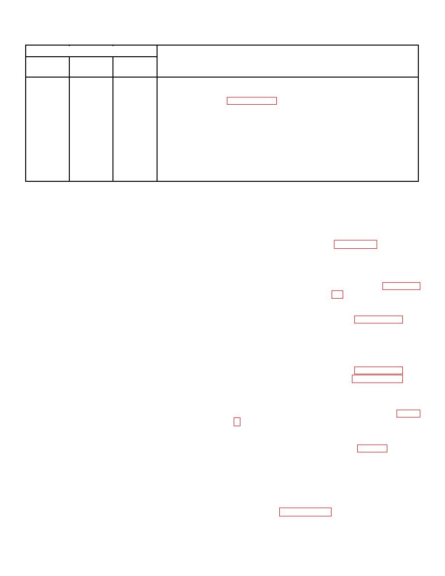
Intervals
Monthly
6-Month
8-Month
Procedure
X
Wiring. Inspect for broken wires, loose or defective lugs, and frayed,
burned, or brittle insulation. Tape frayed wires and replace defective
lugs and wiring (paragraph 141). Report defective wiring to field
maintenance.
X
Load resistors. Inspect for loose connections, cracked or frayed wire
insulation, corroded terminals, loose mounting screws, and indications
of resistor discoloration due to excess heat. Tape frayed insulation,
clean corroded terminals, and tighten loose mounting screws or
connections. Report deficiencies to field maintenance for correction.
X
Fan motors. Inspect motors for dust, dirt, or oil deposits. Inspect
electrical connections for breaks, frayed insulation, or loose
connections.
Section IV. TROUBLESHOOTING
88. METERS INOPERATIVE.
86. GENERAL.
This section provides information useful in
Probable Cause
Possible remedy
diagnosis and correction, inspection, operation, or
No line voltage ....................Check input power cable
failure of the generator test stand, or any of its
and
receptacle
components. Each trouble symptom stated is followed
by a list of probable causes. The possible remedy
Loose or missing meter
Tighten meter links and re-
recommended is described opposite the probable cause.
links
place missing meter links.
Units, parts, or hardware found defective and not
Loose or improper position Tighten and check position
repairable shall be replaced.
ing of connection board
of load links and load dis-
87. LOAD RACK OVERHEATING.
links
connect links (paragraph
Probable Cause
Possible remedy
Loose electrical connection Tighten meter connections.
Obstruction in air intake ......Check
and
remove
on meters
obstructions.
Meter defective ...................Replace (paragraph 91).
Hub of fan blade loose on Tighten setscrew to secure
89. PRESSURE GAGE INOPERATIVE.
motor shaft
to motor shaft. Replace if
defective.
Probable Cause
Possible remedy
Meter connections loose......Tighten
coupling
and
compression
nut
connections.
Tubing bent or cracked........Replace (paragraph 92).
Gage defective....................Replace (paragraph 92).
Section V. CONTROL PANEL ASSEMBLY
90. GENERAL.
(2) Loosen the three captive bolts (7, figure
The control panel provides facilities for testing
dc, three-phase ac, and single-phase ac aircraft power
panel open.
equipment. The terminals, meters, and switches on the
(3) Tag and disconnect electrical leads from
control panel are designed to measure field current, load
terminals of single-phase ammeter (7, figure 7).
current, generated voltage, and dissipated input power
(4) Remove meter from front of panel by four
with proper operation of various switches and meters.
nuts securing single-phase ammeter (7).
Units, parts, or hardware found defective and not
(5) Remove other meters in a similar manner.
repairable shall be replaced.
Note
91. METERS.
Replace high-low frequency meter (9)
a. Removal.
and external impedor box (18) as a
(1) Disconnect power input source and
unit (paragraph 115).
external cables on control panel.
21


