TM 55-1510-222-10
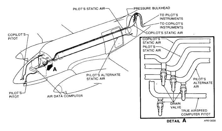
Figure 2-31. Pitot and Static System
pressure inputs from the pilot's pitot and static air
sources, from which aircraft altitude above sea level is
computed. The computed altitude is simultaneously
routed to: the transponder (for encoded transmission to
ground stations) and the pilot's altimeter.
The servoed altimeter displays altitude by a
10,000 foot counter, a 1000 foot counter, and a single
needle pointer which indicates hundreds of feet on a
circular scale in 20 foot increments. Below an altitude
of 10,000 feet, a diagonal warning symbol will appear on
the 10,000 foot counter. The barometric pressure
adjustment knob allows ground supplied pressure values
to be adjusted and displayed in inches Hg or millibars.
If AC power to the altimeter is lost, a warning flag will
appear in the upper center portion of the instrument face
to indicate power loss, unreliable altimeter readings, and
possible failure of encoder transmissions to ground
stations.
2-82.
COPILOT'S ENCODING ALTIMETER.
The copilot's altimeter (figure 2-14) is an
internally lighted, pneumatic instrument, capable of
providing altitude readouts from minus 1,000 to 50,000
feet. Altitude is displayed on the instrument face by
10,000, 1,000, and 100 feet counter drums and a single
needle pointer which indicates hundreds of feet in 20
feet increments. A barometric pressure-setting knob is
provided to simultaneously adjust the baro counters in
inches of mercury (Hg.), and millibars (Mb.). Below an
altitude of 10,000 feet, a crosshatch diagonal symbol
will appear in the 10,000 foot counter. If the barometric
pressure results in an altitude less than sea level, the
word NEG (indicating negative altitude) will appear on
the 10,000 foot counter. If AC power is lost, a warning
flag will appear in the upper center portion of the
instrument face to indicate possible failure of encoder
transmissions to ground stations.
2-83.
VERTICAL SPEED INDICATORS.
Vertical speed indicators are installed separately
on the pilot and copilot sides of the instrument panel
(fig. 2-14). They indicate the speed at which the aircraft
ascends or descends based on changes in atmospheric
pressure. The indicator is a direct reading pressure
instrument requiring no electrical power for operation.
2-76