TM 55-1510-222-10
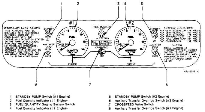
Figure 2-16. Fuel Management Panel
depletion of fuel pressure during starting, energizes the
motive flow valve. When auxiliary fuel is depleted, a
low level float switch de-energizes the motive flow valve
after a 30 to 60 second time delay. This time delay
function prevents cycling of the motive flow valve due to
sloshing fuel. If the motive flow valve or the associated
control circuitry fails, the loss of motive flow pressure
when there is still fuel remaining in the auxiliary fuel
tank, is sensed by a pressure and float switch which
illuminates a caution annunciator placarded #1 NO
FUEL XFR or #2 NO FUEL XFR. During engine start,
the pilot should note that the NO FUEL XFR
annunciator extinguish 30 to 50 seconds after engine
start. The NO FUEL XFR annunciator will not illuminate
if auxiliary tanks are empty. A manual override is
incorporated as a backup for the automatic transfer
system. This is initiated by placing the AUX
TRANSFER switch, located in the fuel management
panel to the OVERRIDE position. This will energize the
transfer control motive flow valve. The transfer systems
are protected by -ampere circuit breakers placarded
AUXILIARY TRANSFER #1 or #2, located in the
overhead circuit breaker panel (fig. 2-6).
NOTE
In turbulence or during maneuvers,
the NO FUEL XFR annunciators may
momentarily
illuminate
after
the
auxiliary fuel has completed transfer.
d.
Fuel Gaging System. The total fuel quantity in
the left or right main system, or left or right auxiliary
tank is measured by a capacitance type fuel gaging
system. Two fuel gages, one for the left and one for the
right fuel system, read fuel quantity in pounds. A
maximum of 3% error may be encountered in each
system. However, the system is compensated for fuel
density changes due to temperature excursions. In
addition to the fuel gages, amber #1 NAC LOW or #2
NAC
LOW
annunciators
on
the
caution/advisory
annunciator
panel
illuminate
when
there
is
approximately 30 minutes of fuel (57 gal) per engine
remaining (on standard day, at sea level, normal cruise
power consumption rate). The fuel gaging system is
protected by individual 5-ampere circuit breakers
placarded QTY IND and FUEL QTY, #1 and #2, located
in the overhead circuit breaker panel (fig. 2-6). A
mechanical spiral float gage (fig. 2-19) is installed in
each auxiliary fuel tank to provide an indication of fuel
level when servicing the tank. The gage is installed on
the auxiliary fuel
2-34