TM 55-1510-222-10
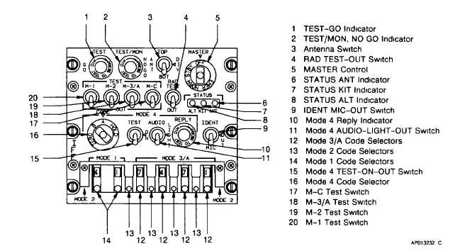
Figure 3-25. Transponder Control Panel (AN/APX-100)
(b) DIV. Selects diverse (both) antennas.
(c) BOT. Selects lower antenna.
(4) RAD TEST-OUT switch. Enables reply to
TEST mode interrogations from test set.
(5) MASTER CONTROL. Selects system
operating mode.
(a) OFF. Deactivates system.
(b) STBY. Activates system warm-up
(standby) mode.
(c) NORM. Activates normal operating
mode.
(d) EMER. Transmits emergency reply
code.
(6) STATUS ANT indicator. Illuminates to
indicate the BIT or MON fault is caused by high VSWR
in antenna.
(7) STATUS KIT indicator. Illuminates to
indicate the BIT or MODN fault is caused by external
computer.
(8) STATUS ALT indicator. Illuminates to
indicate the BIT or MON fault is caused by the altitude
digitizer.
(9) IDENT-MIC-OUT switch. Selects source of
aircraft identification signal.
(a) IDENT. Activates transmission of
identification pulse (IP).
(b) MIC. Enables either control wheel POS
IDENT switch to activate transmission of ident signal
from transponder.
(c) OUT. Disallows outgoing signal.
(10)
MODE
4
reply
annunciator
light.
Illuminates to indicate a reply has been made to a valid
Mode 4 interrogation.
(11)
MODE 4 AUDIO OUT switch. Selects
monitor mode for mode ,4 operation.
(a) AUDIO. Enables sound and sight
monitoring of mode 4 operation.
3-78


