TM 55-1510-222-10
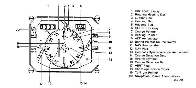
Figure 3-8. Pilot's Horizontal Situation Indicator (RD-650B)
at the fore (upper) and aft (lower) position.
(4)
HDG flag. Indicates loss of reliable
heading information.
(5)
Heading bug. The notched orange
heading bug is positioned on the rotating heading dial by
the remote heading knob, to select and display a
preselected compass heading. Once set to the desired
heading, the heading bug maintains its position on the
heading dial. The difference between the bug and the
fore (upper) lubber line index is the amount of heading
select error applied to the flight director computer. In
the heading mode the ADI will display the proper bank
commands to turn to and maintain this selected
heading.
(6)
Course display. Provides a digital
readout of selected magnetic course.
(7)
Course pointer. The yellow course
pointer is positioned on the heading dial by the remote
course knob, to a magnetic bearing that coincides with
the selected course being flown. The course pointer
rotates with the heading dial to provide a continuous
readout of course error to the computer.
(8)
Bearing pointer. Indicates ADF or
NAV relative bearing as selected by the bearing pointer
source switch.
(9)
ADF annunciator. When illuminated,
indicates ADF bearing information is being displayed.
(10)
Bearing pointer source switch. The
bearing pointer source switch, located on the pilot's HSI,
provides for selecting between ADF or NAV bearing
information as presented by the bearing pointer. Each
push of the select switch alternates selection of ADF or
NAV. Upon power-up, or following long-term power
interruption, NAV is displayed.
(11)
NAV annunciator. When illuminated,
indicates NAV bearing information is being displayed.
(12)
NAV/ flag. Indicates loss of VOR,
TACAN or INS information, or unreliable navigation
signal.
3-20