TM 55-1510-222-10
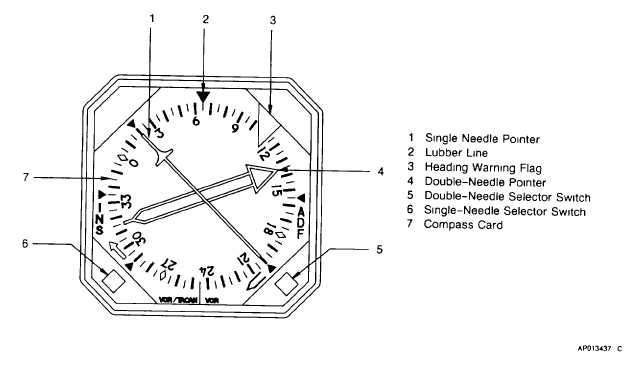
Figure 3-7. Radio Magnetic Indicator (RMI-30)
the in position returns it to the out position. When in the
out position, VOR 2 bearing information is supplied to
the double-needle pointer, and the doubleneedle
indicator, points to the VOR station.
(7)
Single-needle pointer selector switch.
This is a two-position, press to change selector switch,
located on the lower left corner of the RMI. When
depressed to the in position, INS bearing information is
supplied to the single needle, and the single-needle
indicator on the RMI points to INS. Depressing the
switch when it is in the in position returns it to the out
position. When in the out position, VOR 1 or TACAN
bearing information is supplied to the single-needle
pointer, and the singleneedle indicator points to
VOR/TACAN.
(8)
Compass card. This rotating card
repeats gyro stabilized magnetic compass information.
3-16. HORIZONTAL SITUATION INDICATORS.
a.
Description. The pilot and copilot have
separate HSI instruments on respective instrument
panel sections (fig. 2-14). Each HSI combines displays
to provide a map-like presentation of the aircraft position
with respect to magnetic heading. Each indicator
displays
aircraft
heading,
course
deviation,
and
glideslope data. The pilot's HSI allows the desired
course and heading to be input to the autopilot. Course
deviation data is supplied to the HSI by the VOR 1 or
VOR 2 systems, the TACAN, or the INS. Glideslope
data is supplied by the VOR 1 or VOR 2 systems. The
HSI displays warning flags when the VOR, TACAN, INS
or glideslope signals are lost or become unreliable.
b.
Controls/Indicators and Functions, Pilot's
HSI (fig. 3-8) (RD-650B).
(1)
Distance display. Provides digital
displays of TACAN or INS waypoint distance. TACAN
distance is displayed in 1/10 mile increments. INS
distance to waypoint is displayed in whole mile
increments. The display will show dashes when the
distance input data is invalid or absent.
(2)
Rotating
heading
(azimuth)
dial.
Displays gyro stabilized magnetic compass information
on a dial which rotates with the aircraft throughout 360
degrees. The azimuth ring is graduated in 5 degree
increments.
(3)
Lubber line. Fixed heading marks
located
3-19


