TM 55-1510-220-10
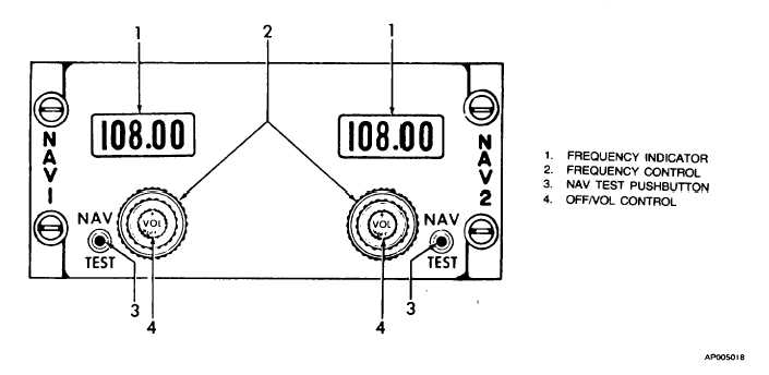
Figure 3-16. VOR Control Panel (VIR-30AGM, VIR-30AG)
(a)
INCREASE. Causes gyro heading
output to increase (move in counterclockwise direction).
(b)
DECREASE. Causes gyro heading
output to decrease (move in clockwise direction).
d.
Normal Operation.
(1)
Alignment procedure:
1.
Gyro
compass
slave-free
switch
SLAVE.
2.
Gyrocompass increase-decrease switch
Hold
switch
momentarily
in
the
direction desired, and then release.
This will place system in fast erect
mode. The gyro will then erect at
approximately 30 degrees per minute.
While in the fast erect mode, the
HEADING flag (HSI) will be in view.
When the HEADING flag retracts from
view, the heading displayed will be the
magnetic heading.
(2)
To determine magnetic heading:
1.
Gyrocompass
slave-free
switch
SLAVE.
2.
RMI rotating heading dial (compass
card) Read heading.
(3)
To determine directional gyro heading:
1.
Gyrocompass slave-free switch FREE.
2.
Gyrocompass increase-decrease switch
Hold until the RMI compass card aligns
with
the
magnetic
heading,
then
release.
3.
Read heading. The heading will agree
with the appropriate HSI.
e.
Shutdown Procedure. Both compass systems are
shut down when the INVERTER No. I and INVERTER No.
2 switch is turned off. (If either inverter is on, both compass
sets will be energized.)
3-24. VOR/LOC NAVIGATION SYSTEM.
a.
Description. The aircraft is equipped with two VOR
systems, controlled by a dual NAV I NAV 2 control panel,
located on the pedestal (fig.
2-8). Either VOR can direct input signals to the flight
director indicator. Controls are shown on figure 3-16. Each
VOR receiver provides a VOR input to a respective RMI,
HSI, and flight director computer. Each glideslope receiver
sends GS flag and pointer deviation information to the HSI
and flight director computer. VOR/LOC indicators may .be
used for navigation during manual control of the aircraft,
Change 2
3-29


