TM 55-1510-220-10
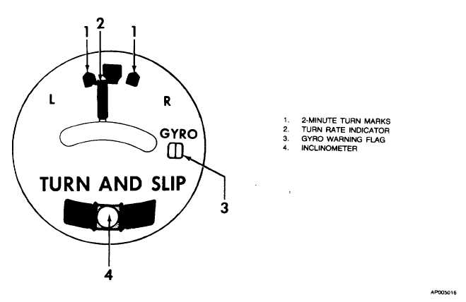
Figure 3-14. Pilot's Turn and Slip Indicator (329T-1)
(3)
GYRO warning. Presence indicates loss of
power to instrument.
(4)
Inclinometer. Indicates lateral acceleration
(side slip) of aircraft.
3-22. COPILOT'S GYRO HORIZON INDICATOR.
a.
Description. The copilot's gyro horizon indicator
(fig. 3-15) is a flight aid which indicates the aircraft's
attitude. The attitude given is in relationship to an artificial
horizon. There are no front panel fuses or circuit breakers
provided for the copilot's gyro horizon indicator.
b.
Indicators and Functions.
(1)
Bank angle index. Reference indicating zero-
degree bank.
(2)
Bank angle pointer. Indicates aircraft bank
angle.
(3)
Bank angle scale. Indicates aircraft bank
angle from zero to 90 degrees with marks at 10, 20, 30, 45,
60, and 90 degrees.
(4)
Horizon line. Affixed to sphere, remains
parallel to the earth's horizon at all times.
(5)
Miniature aircraft. Indicates attitude of
aircraft with respect to the earth's horizon.
(6)
G flag. Presence announces loss of power.
(7)
Sphere. Indicates orientation with earth's axis
at all times.
(8)
Inclinometer. Assists the copilot in making
coordinated turns.
3-23. GYROMAGNETIC COMPASS SYSTEMS.
a.
Description. Two identical compass systems provide
accurate directional information for the aircraft at all latitudes
of the earth. As a heading reference, two modes of operation
are used: directional gyro (FREE) mode, or slaved (SLAVE)
mode. In polar regions of the earth where magnetic heading
references are not reliable, the system is operated in the FREE
mode.
3-27