TM 55-1510-220-10
Section III. NAVIGATION
3-17. DESCRIPTION.
The navigation equipment group provides the pilot and
copilot with instrumentation required to establish and
maintain an accurate flight course and position, and to make
an approach on instruments under Instrument Meteorological
Conditions (IMC). The navigation configuration includes
equipment for determining attitude, position, destination
range and bearing, heading reference and groundspeed.
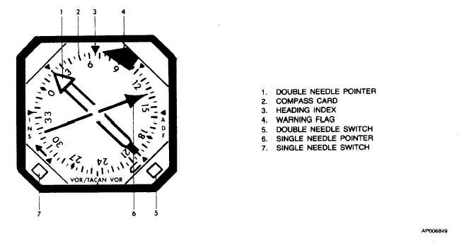
3-18. RADIO MAGNETIC INDICATORS (RMI).
a.
Description. The pilot and copilot are each provided
with identical radio magnetic indicators (RMI) (fig. 3-10),
located on the instrument panel (fig. 2-30). Each unit serves
as a navigational aid for the respective user and, by means of
individual source select switches, will display aircraft
magnetic heading and VOR, TACAN, INS or ADF bearing
information. The pilot's RMI is protected by the 1ampere No.
1 RMI circuit breaker on the overhead circuit breaker panel
(fig. 2-27) and the 1.5-ampere F13 fuse on the No. I junction
box. The copilot's RMI is protected by the 1-ampere No. 2
RMI circuit breaker on the overhead circuit breaker panel and
the 1.5-ampere F9 fuse on the No. 1 junction box.
b.
Controls and Functions.
(1)
Pilot's COMPASS No.1 No.2 switch. Selects
desired source of magnetic heading information for display on
pilot's HSI and copilot's RMI.
(a)
No.1. Selects compass system No.1 for
display control.
(b)
No.2. Selects compass system No.2 for
display control.
(2)
Copilot's
COMPASS
No.l-No.2
switch.
Selects desired source of magnetic heading information for
display on copilot's HSI and pilot's RMI.
(a)
No.1. Selects compass system No.1 for
display.
(b)
No.2. Selects compass system No.2 for
display.
Figure 3-10. Radio Magnetic Indicator (RMI) (332C-10)
Change 2
3-21